Operator’s Manual 125C 125L Please read the operator’s manual carefully and make sure you understand the instructions before using the machine.
CONTENTS Contents The Emissions Compliance Period referred to on the Emissions Compliance label indicates the number of operating hours for which the engine has been shown to meet Federal emissions requirements. Category C = 50 hours, B= 125 hours, and A = 300 hours. CONTENTS Contents . . . . . . . . . . . . . . . . . . . . . . . . 2 Note the following before starting . . . . 2 KEY TO SYMBOLS Symbols . . . . . . . . . . . . . . . . . . . . . . . . . 3 SAFETY INSTRUCTIONS Personal protective equipment . .
KEY TO SYMBOLS Symbols Only intended for trimmer heads. WARNING! Clearing saws, brushcutters and trimmers can be dangerous! Careless or incorrect use can result in serious or fatal injury to the operator or others. Other symbols/decals on the machine refer to special certification requirements for certain markets. Please read the operator’s manual carefully and make sure you understand the instructions before using the machine.
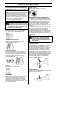
SAFETY INSTRUCTIONS Personal protective equipment FIRST AID KIT Always have a first aid kit nearby. IMPORTANT! Whenever you use a clearing saw, brushcutter or trimmer you must wear personal protective equipment that is approved by the authorities. Personal protective equipment does not eliminate the risk of accidents, but it can reduce the effects of an injury in the event of an accident. Ask your dealer for help when choosing protective equipment.
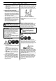
SAFETY INSTRUCTIONS WARNING! Mufflers fitted with catalytic converters get very hot during use and remain so for some time after stopping. This also applies at idle speed. Contact can result in burns to the skin. Remember the risk of fire! Cutting attachment guard This guard is intended to prevent loose objects from being thrown towards the operator. The guard also protects the operator from accidental contact with the cutting attachment.
SAFETY INSTRUCTIONS Throttle lock Stop switch S Make sure the throttle control is locked at the idle setting when the throttle lock is released. S Start the engine and make sure the engine stops when you push and hold the stop switch. Cutting attachment guard S Press the throttle lock and make sure it returns to its original position when you release it. S Ensure that the guard is undamaged and is not cracked.
SAFETY INSTRUCTIONS Cutting equipment Trimmer head This section describes how to choose and maintain your cutting equipment in order to: S Obtain maximum cutting performance. S Extend the life of cutting equipment. S Only use the recommended cutting attachments. See the section on “Technical data”. General rules S Smaller machines generally require small trimmer heads and vice versa.
SAFETY INSTRUCTIONS General safety precautions WARNING! A faulty cutting attachment may increase the risk of accidents. IMPORTANT! S The machine is only designed for trimming grass. S The only accessories you can operate with this engine unit are the cutting attachments we recommend in the “Technical data” section. S Never use wire, rope, string, etc.
SAFETY INSTRUCTIONS 3. Make sure you can move and stand safely. Check the area around you for possible obstacles (roots, rocks, branches, ditches, etc.) in case you have to move suddenly. Take great care when working on sloping ground. S If the machine is leaking fuel. Check regularly for leaks from the fuel cap and fuel lines. S Avoid all skin contact with fuel. Fuel is a skin irritant and may even cause skin changes.
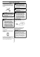
SAFETY INSTRUCTIONS Clearing Sweeping S The clearing technique removes all unwanted vegetation. Keep the trimmer head just above the ground and tilt it. Let the end of the trimmer line strike the ground around trees, posts, statues and the like. CAUTION! This technique increases the wear on the trimmer line. S The fan effect of the rotating line can be used for quick and easy clearing up. Hold the trimmer line parallel to and above the area to be swept and move the tool to and fro.
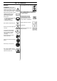
KNOW YOUR TRIMMER 1 2 3 6 125L 8 5 4 10 9 11 16 125C 1 7 15 13 14 12 4 17 1 18 KNOW YOUR TRIMMER 1. Trimmer head 2. Grease filler cap 3. Bevel gear 4. Cutting attachment guard 5. Shaft 6. Loop handle 7. Throttle control 8. Stop switch 9. Throttle lock 10.Cylinder cover 11. 12. 13. 14. 15. 16. 17. 18. 19.
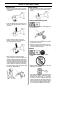
ASSEMBLY Make sure unit is assembled correctly as shown in this manual. Fitting the trimmer guard and trimmer head (Model 125C) Fitting the loop handle S Fit the correct trimmer guard (A) for use with the trimmer head. Hook the trimmer guard/combination guard onto the fitting on the shaft and secure with the wing nut (B). S Position the handle on the shaft. Note that the handle must be mounted between the two arrows on the shaft.
FUEL HANDLING Fuel CAUTION! The machine is equipped with a two--stroke engine and must always be run using a mixture of gasoline and two-stroke engine oil. It is important to accurately measure the amount of oil to be mixed to ensure that the correct mixture is obtained. When mixing small amounts of fuel, even small inaccuracies can drastically affect the ratio of the mixture. S Always start by flling half the amount of the gasoline to be used. Then add the entire amount of oil.
STARTING AND STOPPING Cold engine S Clean the area around the fuel cap. Contamination in the tank can cause operating problems. S Ensure that the fuel is well mixed by shaking the container before filling the tank. Air purge: Press the air purge diaphragm 6 -- 10 times until fuel begins to fill the diaphragm. The diaphragm need not be completely filled. Check before starting S Inspect the unit before each use. Replace damaged parts. Check for fuel leaks. Make sure all fasteners are in place and secure.
STARTING AND STOPPING Warm engine With a warm engine, squeeze and hold the throttle trigger. Pull starter rope sharply while squeezing throttle trigger until engine runs. Stopping Stop the engine by pushing and holding the stop switch in the STOP position until the engine stops. WARNING! When the engine is started with the choke in the closed position the cutting attachment will start to rotate immediately.
MAINTENANCE The owner is responsible for the performance of all required maintenance as defined in the operator’s manual. Carburetor Your Husqvarna product has been designed and manufactured to specifications that reduce harmful emissions. After the engine has used 8--10 tanks of fuel, the engine will be run--in. To ensure that it continues to run at peak performance and to minimize harmful exhaust emissions after the run--in period, ask your servicing dealer to adjust your carburetor.
MAINTENANCE 0.024″ (0.6 mm) Muffler bolts CAUTION! Never use a machine that has a faulty or loose muffler. Ensure the muffler bolts are tight. Air filter WARNING! Mufflers fitted with catalytic converters get very hot during use and remain so for some time after stopping. This also applies at idle speed. Contact can result in burns to the skin.
MAINTENANCE Weekly maintenance S Check the starter and starter cord. S Clean the carburetor area. S Clean the outside of the spark plug. Remove it and check the electrode gap. Adjust the gap to 0.024″ (0.6 mm), or replace the spark plug. Use resistor spark plug Champion RCJ--6Y or equivalent. S Clean the cooling fins on the cylinder and check that the air intake near the starter is not blocked. S Check that the bevel gear is filled with grease up to 3/4 full. Use special grease. S Clean the air filter.
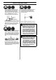
Trimmer Head Line Loading Instructions 6m 20i 3m 10i 19
TECHNICAL DATA Technical data Engine Cylinder volume, cu.in./cm3 Cylinder bore, inch/mm Stroke, inch/mm Idle speed, rpm Recommended max. speed, rpm Speed of output shaft, rpm Max. engine output, acc. to ISO 8893, hp/kW Catalytic converter muffler Speed--regulated ignition system Ignition system Manufacturer/type of ignition system Spark plug 125C 125L 1.7/28 1.4/35 1.130/28.7 2,800--3,200 10,000 8,000 1.1/0.8 Yes No 1.7/28 1.4/35 1.130/28.7 2,800--3,200 11,000 8,000 1.1/0.
WARRANTY STATEMENT SECTION 1: LIMITED WARRANTY THESE PRODUCTS EXCEPT TO THE EXTENT PROHIBITED BY APPLICABLE LAW. ANY IMPLIED WARRANTY OR MERCHANTABILITY OR FITNESS FOR A PARTICULAR PURPOSE ON THESE PRODUCTS IS LIMITED IN DURATION TO THE WARRANTY PERIOD AS DEFINED IN THE LIMITED WARRANTY STATEMENT. HUSQVARNA RESERVES THE RIGHT TO CHANGE OR IMPROVE THE DESIGN OF THE PRODUCT WITHOUT NOTICE, AND DOES NOT ASSUME OBLIGATION TO UPDATE PREVIOUSLY MANUFACTURED PRODUCTS.
U.S. EPA / CALIFORNIA / ENVIRONMENT CANADA EMISSION CONTROL WARRANTY STATEMENT YOUR WARRANTY RIGHTS AND OBLIGATIONS: WARRANTY COMMENCEMENT DATE: The U.S. Environmental Protection Agency, California Air Resources Board, Environment Canada and HUSQVARNA are pleased to explain the emissions control system warranty on your year 2005 and later small off--road engine. In California, all small off--road engines must be designed, built, and equipped to meet the State’s stringent anti--smog standards.
U.S. EPA / CALIFORNIA / ENVIRONMENT CANADA EMISSION CONTROL WARRANTY STATEMENT MAINTENANCE, REPLACEMENT AND REPAIR OF EMISSION RELATED PARTS: Any HUSQVARNA approved replacement part used in the performance of any warranty maintenance or repair on emission related parts will be provided without charge to the owner if the part is under warranty. EMISSION CONTROL WARRANTY PARTS LIST: Carburetor, Ignition System: Spark Plug (covered up to maintenance schedule), Ignition Module.