
Operators Manual
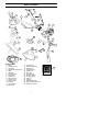
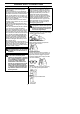
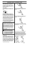
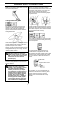

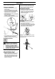
Table Of Contents
- SYMBOL EXPLANATION
- CONTENTS
- WHAT IS WHAT?
- GENERAL SAFETY PRECAUTIONS
- ASSEMBLY
- FUEL HANDLING
- STARTING AND STOPPING
- WORKING TECHNIQUES
- MAINTENANCE
- TECHNICAL DATA
- DECLARATION OF CONFORMITY relating to 2000/14/EC
- DECLARATION OF CONFORMITY relating to 98/37/EC
- Trimmer Head Line Loading Instructions
- Plastic Blades (Tri Cut)

4
WHAT IS WHAT?
1. Blade 16. Air filter cover
2. Grease filler cap 17. Handle adjustment
3. Bevel gear 18. Locking nut
4. Cutting attachment guard 19. Support flange
5. Shaft 20. Support cup
6. Handlebar 21. Drive disc
7. Throttle control 22. Trimmer head
8. Stop switch 23. Socket spanner
9. Throttle lock 24. Transport guard
10. Harness clamp 25. Allen key
11. Cylinder cover 26. Harness
12. Starter handle 27. Start throttle button
13. Fuel tank 28. Adjusting the throttle wire
14. Choke control 29. Operator’ s manual
15. Primer bulb
What is what?
5
2
9
10
6
16
21
23
25
1
3
8
11
15
13
14
7
12
29
17
4
4
4
26
22
18
19
20
1
21
24
28
27