Operator′s manual 132R 133R 142R 143R Please read the operator’s manual carefully and make sure you understand the instructions before using the machine.
KEY TO SYMBOLS Symbols Noise emission to the environment according to the European Community’s Directive. The machine’s emission is specified in chapter Technical data and on label. WARNING! Clearing saws, brushcutters and trimmers can be dangerous! Careless or incorrect use can result in serious or fatal injury to the operator or others. Other symbols/decals on the machine refer to special certification requirements for certain markets.
CONTENTS Contents KEY TO SYMBOLS Symbols ....................................................................... CONTENTS Contents ...................................................................... Note the following before starting: ................................ INTRODUCTION Dear Customer, ............................................................ WHAT IS WHAT? What is what on the brushcutter? (132R, 133R) .......... WHAT IS WHAT? What is what on the brushcutter? (142R, 143R) ..........
INTRODUCTION Dear Customer, Congratulations on your choice to buy a Husqvarna product! Husqvarna is based on a tradition that dates back to 1689, when the Swedish King Charles XI ordered the construction of a factory on the banks of the Husqvarna River, for production of muskets. The location was logical, since water power was harnessed from the Huskvarna River to create the water-powered plant.
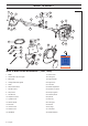
WHAT IS WHAT? 1 3 8 2 6 9 7 10 5 22 4 15 11 17 16 24 12 25 31 14 26 18 29 19 30 13 20 28 1 27 23 21 21 4 4 What is what on the brushcutter? (132R, 133R) 1 Blade 17 Clutch cover 2 Grease filler cap, bevel gear 18 Locking nut 3 Bevel gear 19 Support flange 4 Cutting attachment guard 20 Support cup 5 Shaft 21 Drive disc 6 Start throttle button 22 Handle adjustment 7 Throttle control 23 Operator′s manual 8 Stop switch 24 Transport guard 9 Throttle lock 25 Socket
WHAT IS WHAT? 1 3 8 2 6 9 7 5 22 15 10 11 17 31 4 32 16 12 14 18 19 24 20 25 29 30 13 1 26 23 27 21 28 4 31 What is what on the brushcutter? (142R, 143R) 1 Blade 17 Clutch cover 2 Grease filler cap, bevel gear 18 Locking nut 3 Bevel gear 19 Support flange 4 Cutting attachment guard 20 Support cup 5 Shaft 21 Drive disc 6 Start throttle button 22 Handle adjustment 7 Throttle control 23 Operator′s manual 8 Stop switch 24 Transport guard 9 Throttle lock 25 Socket
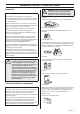
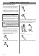
GENERAL SAFETY PRECAUTIONS Important IMPORTANT! The machine is only designed for trimming grass. The only accessories you can operate with this engine unit are the cutting attachments we recommend in the chapter on Technical data. ! WARNING! Listen out for warning signals or shouts when you are wearing hearing protection. Always remove your hearing protection as soon as the engine stops.
GENERAL SAFETY PRECAUTIONS Machine′s safety equipment Press the throttle lock and make sure it returns to its original position when you release it. This section describes the machine′s safety equipment, its purpose, and how checks and maintenance should be carried out to ensure that it operates correctly. See the ”What is what?” section to locate where this equipment is positioned on your machine.
GENERAL SAFETY PRECAUTIONS Cutting attachment guard This guard is intended to prevent loose objects from being thrown towards the operator. The guard also protects the operator from accidental contact with the cutting attachment. Check that the vibration damping element is undamaged and securely attached. ! Check that the guard is undamaged and not cracked. Replace the guard if it has been exposed to impact or is cracked. Always use the recommended guard for the cutting attachment you are using.
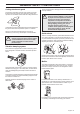
GENERAL SAFETY PRECAUTIONS Never use a machine that has a faulty muffler. Locking nut A locking nut is used to secure some types of cutting attachment. Regularly check that the muffler is securely attached to the machine. If the muffler on your machine is fitted with a spark arrestor mesh this must be cleaned regularly. A blocked mesh will cause the engine to overheat and may lead to serious damage.
GENERAL SAFETY PRECAUTIONS Sharpening grass cutters and grass blades • See the cutting attachment packaging for correct sharpening instructions. • Sharpen blades and cutters using a single-cut flat file. • Sharpen all edges equally to maintain the balance of the blade. ! WARNING! Always discard a blade that is bent, twisted, cracked, broken or damaged in any other way. Never attempt to straighten a twisted blade so that it can be reused. Only use original blades of the specified type.
ASSEMBLY Fitting the main body Fitting blades and trimmer heads Connect the engine (A) to the tube (B) with four screws (C). C B C ! A WARNING! When fitting the cutting attachment it is extremely important that the raised section on the drive disc/support flange engages correctly in the centre hole of the cutting attachment. If the cutting attachment is fitted incorrectly it can result in serious and/or fatal personal injury.
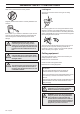
ASSEMBLY Fitting the guard extension 133R: Hook the blade guard/combination guard (A) onto the fitting on the shaft and secure with the bolt (L). 143R CAUTION! The guard extension shall always be fitted when using the trimmer head/plastic blades and combination guard. The guard extension shall always be removed when using the grass blade and combination guard. Enter the guard extension guide in the slot of the combination guard.
ASSEMBLY • Fit the nut (G). The nut must be tightened to a torque of 35-50 Nm (3.5-5 kpm). Use the socket spanner in the tool kit. Hold the shaft of the spanner as close to the blade guard as possible. To tighten the nut, turn the spanner in the opposite direction to the direction of rotation (Caution! left-hand thread). 132R 143R: Fit the correct trimmer guard (A) for use with the trimmer head. CAUTION! Ensure that the guard extension is fitted.
ASSEMBLY Cable adjustment Spreading the load on your shoulders • Throttle cable should be paralleled to flexible shaft. In case of twisting, they should be restored by parallel. • Throttle cable should be adjusted under the bended flexible shaft. A well-adjusted harness and machine makes work much easier. Adjust the harness for the best working position. Tension the side straps so that the weight is evenly distributed across both shoulders.
FUEL HANDLING Fuel safety Petrol Never start the machine: 1 If you have spilt fuel on it. Wipe off the spillage and allow remaining fuel to evaporate. 2 If you have spilt fuel on yourself or your clothes, change your clothes. Wash any part of your body that has come in contact with fuel. Use soap and water. 3 If the machine is leaking fuel. Check regularly for leaks from the fuel cap and fuel lines. CAUTION! Always use a quality petrol/oil mixture at least 90 octane (RON).
FUEL HANDLING Fuelling Mixing • Always mix the petrol and oil in a clean container intended for fuel. • Always start by filling half the amount of the petrol to be used. Then add the entire amount of oil. Mix (shake) the fuel mixture. Add the remaining amount of petrol. • ! Mix (shake) the fuel mixture thoroughly before filling the machine’s fuel tank. WARNING! Taking the following precautions, will lessen the risk of fire: Do not smoke or place hot objects near fuel.
STARTING AND STOPPING Check before starting • • Check the blade to ensure that no cracks have formed at the bottom of the teeth or by the centre hole. The most common reason why cracks are formed is that sharp corners have been formed at the bottom of the teeth while sharpening or that the blade has been used with dull teeth. Discard a blade if cracks are found.
STARTING AND STOPPING Hold the body of the machine on the ground using your left hand (CAUTION! Not with your foot!). Grip the starter handle, slowly pull out the cord with your right hand until you feel some resistance (the starter pawls grip), now quickly and powerfully pull the cord. Never twist the starter cord around your hand. Repeat pulling the cord until the engine starts. When the engine starts.
WORKING TECHNIQUES General working instructions IMPORTANT! This section describes the basic safety precautions for working with clearing saws and trimmers. If you encounter a situation where you are uncertain how to proceed you should ask an expert. Contact your dealer or your service workshop. 7 Switch off the engine before moving to another area. Fit the transport guard before carrying or transporting the equipment any distance.
WORKING TECHNIQUES Grass clearing using a grass blade • Grass blades and grass cutters must not be used on woody stems. • A grass blade is used for all types of tall or coarse grass. • The grass is cut down with a sideways, swinging movement, where the movement from right-to-left is the clearing stroke and the movement from left-to-right is the return stroke. Let the left-hand side of the blade (between 8 and 12 o’clock) do the cutting.
MAINTENANCE Carburettor Muffler Your Husqvarna product has been designed and manufactured to specifications that reduce harmful emissions. After the engine has used 8-10 tanks of fuel the engine will be run-in. To ensure that it continues to run at peak performance and to minimise harmful exhaust emissions after the running-in period, ask your dealer/service workshop (who will have a rev counter at their disposal) to adjust your carburettor.
MAINTENANCE Air filter Bevel gear The air filter must be regularly cleaned to remove dust and dirt in order to avoid: The bevel gear is filled with the right quantity of grease at the factory. However, before using the machine you should check that the bevel gear is filled three-quarters full with grease. Use HUSQVARNA special grease. • Carburettor malfunctions • Starting problems • Loss of engine power • Unnecessary wear to engine parts. • Excessive fuel consumption.
MAINTENANCE Maintenance schedule The following is a list of the maintenance that must be performed on the machine. Most of the items are described in the Maintenance section. The user must only carry out the maintenance and service work described in this Operator’s Manual. More extensive work must be carried out by an authorised service workshop. Maintenance Daily maintenance Clean the outside of the machine. X Check that the harness is not damaged.
TECHNICAL DATA Technical data Technical data 132R 133R 142R 143R Cylinder displacement, cm3 31,8 31,8 41,5 41,5 Cylinder bore, mm 38 38 40 40 Stroke, mm 28 28 33 33 Idle speed, rpm 3000 3000 2600 2600 Recommended max. fast idle speed, rpm 11000 11000 10400 10400 Speed of output shaft, rpm 8250 7530 8060 8060 Max. engine output, acc.
TECHNICAL DATA 132R Approved accessories Type Cutting attachment guard, Art. no. Grass blade Grass 255-4 (Ø 255 4 teeth) 531 00 78-34 Type Cutting attachment guard, Art. no. 133R Approved accessories Grass blade Trimmer head Grass 255-4 (Ø 255 4 teeth) 503 93 42-02 T35 503 93 42-02 S35 503 93 42-02 T25 503 93 42-02 Superauto II 503 93 42-02 142R Approved accessories Type Cutting attachment guard, Art. no.
Trimmy SII 1 2,4-3,3 mm .095"-.
T25 2 3 2,0-2,4 mm .079-.
S35 2 3 2,4-2,7 mm .095-.
S35 3 2 2,4-2,7 mm .095-.
T35 2 3 2,4-2,7 mm .095-.
T45 2 3 2,7-3,3 mm .106-.
Super Auto II Super Auto II 1" 1 2 3 4 2,4 mm .
1150174-26 ´®z+R1J¶6r¨ ´®z+R1J¶6r¨ 2006-02-07