330SB-XLSb Owner's Manual / 96193004100 / 2008-11
IMPORTANT Safe Operation Practices for Walk-Behind Snow Throwers This snow thrower is capable of amputating hands and feet and throwing objects. Failure to observe the following safety instructions could result in serious injury. WARNING: Snow throwers have exposed rotating parts, which can cause severe injury from contact, or from material thrown from the discharge chute. Keep the area of operation clear of all persons, small children and pets at all times including startup.
6. When cleaning, repairing or inspecting the snow thrower, stop the engine and make certain the collector/impeller and all moving parts have stopped. Disconnect the spark plug wire and keep the wire away from the plug to prevent someone from accidentally starting the engine. 7. Do not run the engine indoors, except when starting the engine and for transporting the snow thrower in or out of the building. Open the outside doors; exhaust fumes are dangerous. 8.
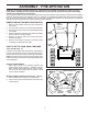
PARTS PACKED SEPARATELY IN CARTON (1) FUEL STABILIZER PACKET (1) MULTIWRENCH (180684) (1) SAFTEY IGNITION KEY (193071) (1) POWER CORD (198563) (1) AUGER CONTROL ROD (1) TRACTION DRIVE CONTROL ROD (1) DISCHARGE CHUTE EXTRA SHEAR BOLTS AND NUTS (6) SHEAR BOLTS 1/4-20 x 1-3/4 (198636) (6) SPACERS (198638) (6) LOCKNUTS 1/4-20 (73800400) ROTATOR HEAD MOUNTING (3) RETAINER SPRINGS (169675) (1) WASHER 3/8 (19131316) (1) LOCKNUT 3/8 (73800600) CHUTE DEFLECTOR REMOTE CONTROL (1) LOCKNUT 5/16-18 (751153)
ASSEMBLY / PRE-OPERATION Read these instructions and this manual in its entirety before you attempt to assemble or operate your new snow thrower. Reading the entire manual will familiarize you with the unit, which will assist you in assembly, operation and maintenance of the product. Your new snow thrower has been assembled at the factory with the exception of those parts left unassembled for shipping purposes. All parts such as nuts, washers, bolts, etc.
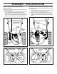
ASSEMBLY / PRE-OPERATION INSTALL AUGER CONTROL ROD (See Figs. 5 and 6) The auger control rod has the short loop on the end of the spring as shown. 1. Slide rubber sleeve up rod and hook end of spring into control arm with loop opening up as shown. 2. With top end of rod positioned under right side of control panel, push down on rod and insert end of rod into hole in auger control bracket. Secure with retainer spring. INSTALL TRACTION DRIVE CONTROL ROD (See Figs.
ASSEMBLY / PRE-OPERATION INSTALL CHUTE DEFLECTOR REMOTE CONTROL (See Figs. 8 and 9) 1. Install remote cable bracket to discharge chute with 5/16-18 carriage bolt and 5/16-18 locknut as shown. Tighten securely. 2. Install remote cable eyelet to chute deflector with 1/4-20 shoulder bolt, nylon friction washer and 1/4-20 locknut as shown. Tighten securely. 3. Install spring hooks between hex nuts on chute rotator head and into hole in chute deflector as shown.
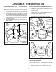
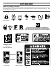
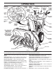
OPERATION KNOW YOUR SNOW THROWER READ THIS OWNER'S MANUAL AND ALL SAFETY RULES BEFORE OPERATING YOUR SNOW THROWER. Compare the illustrations with your snow thrower to familiarize yourself with the location of various controls and adjustments. Save this manual for future reference. These symbols may appear on your snow thrower or in literature supplied with the product. Learn and understand their meaning.
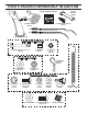
OPERATION GASOLINE FILLER CAP AUGER CONTROL LEVER ELECTRIC START BUTTON MUFFLER RECOIL (AUXILIARY) STARTER HANDLE DISCHARGE CHUTE CONTROL LEVER DRIVE SPEED CONTROL LEVER TRACTION DRIVE CONTROL LEVER CHUTE DEFLECTOR CHOKE CONTROL LH TURN TRIGGER PRIMER SAFETY IGNITION KEY DEFLECTOR REMOTE CONTROL LEVER FUEL SHUT-OFF VALVE DISCHARGE CHUTE THROTTLE / ENGINE CONTROL LIGHT HANDLE KNOB CLEAN-OUT TOOL NOTE: ITEMS ABOVE ARE SHOWN IN THEIR TYPICAL LOCATION ON THE ENGINE.
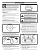
OPERATION The operation of any snow thrower can result in foreign objects thrown into the eyes, which can result in severe eye damage. Always wear safety glasses or eye shields while operating your snow thrower or performing any adjustments or repairs. We recommend standard safety glasses or a wide vision safety mask worn over spectacles. HOW TO USE YOUR SNOW THROWER Know how to operate all controls before adding fuel or attempting to start the engine.
OPERATION AUGER CONTROL LEVER SPEED and DIRECTION are controlled by the drive speed control lever. • Move speed control lever to desired position AFTER engaging the traction drive control lever. CAUTION: Do not move speed control lever unless engine is running. Damage to the snow thrower can result. FIG. 15 USING THE CLEAN-OUT TOOL (See Fig. 16) In certain snow conditions, the discharge chute may become clogged with ice and snow. Use the clean-out tool to dislodge this blockage.
OPERATION NOTE: It is not recommended to operate the snow thrower over gravel or rocky surfaces. Objects such as gravel, rocks or other debris, can easily be picked up and thrown by the impeller, which can cause serious personal injury, property damage or damage to the snow thrower. • If snow thrower must be operated over gravel surface, use extra caution and be sure skid plates are adjusted to lowest (highest scraper clearance) position. 1. Shut off engine and wait for all moving parts to stop. 2.
OPERATION CAUTION: Alcohol blended fuels (called gasohol or using ethanol or methanol) can attract moisture which leads to separation and formation of acids during storage. Acidic gas can damage the fuel system of an engine while in storage. To avoid engine problems, the fuel system should be emptied before storage of 30 days or longer. Drain the gas tank, start the engine and let it run until the fuel lines and carburetor are empty. Use fresh fuel next season.
WARNING: Do not operate snow thrower if weather conditions impair visibility. Throwing snow during a heavy, windy snowstorm can blind you and be hazardous to the safe operation of the snow thrower. MAINTENANCE LUBRICATION CHART GENERAL RECOMMENDATIONS The warranty on this snow thrower does not cover items that have been subjected to operator abuse or negligence. To receive full value from the warranty, operator must maintain snow thrower as instructed in this manual.
MAINTENANCE SNOW THROWER Check the crankcase oil level before starting the engine and after each five (5) hours of continuous use. Tighten oil fill cap / dipstick securely each time you check the oil level. TO CHANGE ENGINE OIL Determine temperature range anticipated before next oil change. All oil must meet API service classification SG–SL. • Be sure snow thrower is on level surface. • Oil will drain more freely when warm. • Catch oil in a suitable container.
SERVICE AND ADJUSTMENTS WARNING: To avoid serious injury, before performing any service or adjustments: 1. Be sure throttle is in STOP position. 2. Remove safety ignition key. 3. Make sure the augers and all moving parts have completely stopped. 4. Disconnect spark plug wire from spark plug and place wire where it cannot come in contact with plug. SNOW THROWER TO ADJUST SNOW THROWER HEIGHT See “TO ADJUST SKID PLATES” and “SCRAPER BAR” in the Operation section of this manual.
SERVICE AND ADJUSTMENTS TO REPLACE BELTS (See Fig. 25) The auger and traction drive belts are not adjustable. If the belts are damaged or begin to slip from wear, they should be replaced. It is recommended that the belt(s) be replaced by a qualified service center. NOTE: It is recommended that both the auger and traction drive belt be replaced at the same time.
TO REMOVE WHEELS (See Fig. 26) • Remove the klik pin and remove wheel from axle. IMPORTANT: When installing wheel, be sure to use the axle hole closest to the end of the shaft – do not use the hole in the wheel hub (if equipped). Inner hole in axle and hole in wheel hub are not used for your model snow thrower. KLIK PIN (INSTALL IN OUTER HOLE OF AXLE ONLY) OUTER HOLE AXLE WHEEL HUB WHEEL FIG.
TROUBLESHOOTING See appropriate section in manual unless directed to a qualified service center. PROBLEM Does not start CAUSE 1. Fuel shut-off valve (if so equipped) in OFF position. 2. Safety ignition key is not inserted. 3. Out of fuel. 4. Throttle in STOP position. 5. Choke in OFF position. 6. Primer not depressed. 7. Engine is flooded. 8. Spark plug wire is disconnected. 9. Bad spark plug. 10. Stale fuel. 11. Water in fuel. CORRECTION 1. Turn fuel shut-off valve to OPEN position. 2.
AUGER HOUSING / IMPELLER ASSEMBLY REPAIR PARTS SNOW THROWER - MODEL NO. 1330SB-XLSB (96193004100), PRODUCT NO. 961 93 00-41 5 11 11 6 7 15 14 16 12 13 8 11 4 12 3 17 10 11 1 9 2 33 32 34 30 31 31 26 36 29 28 27 23 22 21 20 25 35 24 23 22 2 (EXPLODED) 21 18 19 01.07.
AUGER HOUSING / IMPELLER ASSEMBLY REPAIR PARTS SNOW THROWER - MODEL NO. 1330SB-XLSB (96193004100), PRODUCT NO. 961 93 00-41 KEY NO. PART NO.
AUGER HOUSING / IMPELLER ASSEMBLY REPAIR PARTS SNOW THROWER - MODEL NO. 1330SB-XLSB (96193004100), PRODUCT NO. 961 93 00-41 1 3 (5x) 4 (5x) KEY NO. PART NO. DESCRIPTION 1 2 3 4 532 42 17-13 532 40 76-45 872 27 05-05 532 15 53-77 AUGER HOUSING SCRAPPER BAR CARRIAGE BOLT 5/16−18 X .625 NUT 5/16−18 KEY NO. PART NO. DESCRIPTION 1 2 532 42 17-26 532 42 17-27 AUGER ASSEMBLY 30 LH AUGER ASSEMBLY 30 RH 2 01.07.023-B 2 1 01.07.016-A NOTE: All component dimensions given in U.S. inches.
AUGER HOUSING / IMPELLER ASSEMBLY REPAIR PARTS SNOW THROWER - MODEL NO. 1330SB-XLSB (96193004100), PRODUCT NO. 961 93 00-41 2 3 1 1 2 KEY NO. 1 2 3 PART NO. 532 18 81-70 532 41 18-33 532 17 95-82 DESCRIPTION PLASTIC RETAINER AUGER BALL BEARING SCREW 5/16−18 X 1.00 3 01.07.007-A 2 3 1 3 2 01.11.002-A KEY NO. 1 2 3 PART NO. 532 40 78-34 872 27 05-06 532 75 11-53 DESCRIPTION SKID PLATE CARRIAGE BOLT 5/16−18 X .750 NUT 5/16−18 1 NOTE: All component dimensions given in U.S. inches.
AUGER HOUSING / IMPELLER ASSEMBLY REPAIR PARTS SNOW THROWER - MODEL NO. 1330SB-XLSB (96193004100), PRODUCT NO. 961 93 00-41 1 4 5 1 3 4 4 3 5 3 2 2 3 KEY NO. PART NO. DESCRIPTION 1 2 3 4 5 532 18 47-47 872 27 05-06 532 17 92-46 810 04 05-00 532 12 86-38 DRIFT CUTTER BAR CARRIAGE BOLT 5/16−18 X .750 PLASTIC WASHER LOCKWASHER 5/16 NUT 5/16−18 KEY NO. PART NO. DESCRIPTION 1 2 3 4 532 18 25-16 872 11 05-10 532 75 11-53 819 11 22-06 WEIGHT BAR CARRIAGE BOLT 5/16−18 X 1.
CONTROL PANEL / DISCHARGE CHUTE REPAIR PARTS SNOW THROWER - MODEL NO. 1330SB-XLSB (96193004100), PRODUCT NO. 961 93 00-41 5 7 16 3 18 17 19 6 19 6 *15 KEY NO. PART NO.
CONTROL PANEL / DISCHARGE CHUTE REPAIR PARTS SNOW THROWER - MODEL NO. 1330SB-XLSB (96193004100), PRODUCT NO. 961 93 00-41 2 2 1 *3 *6 *6 KEY NO. PART NO. DESCRIPTION 1 2 *3 *4 *5 *6 532 42 11-60 817 50 10-10 532 42 06-78 532 42 11-61 532 42 06-75 532 42 11-62 LEVER/CABLE ROTATOR ASSEMBLY GRAY SCREW 10−24 X .625 ROTATOR HEAD ROTATOR PIVOT BRACKET PULLEY PIVOT CABLE ASSEMBLY GRAY *4 01.09.008-B *5 NOTES: 1. ITEMS INDICATED WITH AN * ARE LISTED AS REFERENCE FOR SERVICE PARTS ONLY. 2 1 KEY NO.
HANDLES REPAIR PARTS SNOW THROWER - MODEL NO. 1330SB-XLSB (96193004100), PRODUCT NO. 961 93 00-41 10 2 11 8 4 7 9 9 5 6 7 1 3 13 8 12 13 14 14 12 KEY NO. 1 2 3 4 5 6 7 8 9 10 11 12 13 14 PART NO. 532 41 55-39 532 42 17-06 532 42 17-07 532 41 55-46 532 42 14-92 532 41 26-77 532 41 26-80 532 16 96-75 817 06 04-08 532 41 42-80 532 41 42-81 532 17 88-99 819 13 13-16 872 12 06-18 01.08.
HANDLES REPAIR PARTS SNOW THROWER - MODEL NO. 1330SB-XLSB (96193004100), PRODUCT NO. 961 93 00-41 10 1 5 6 10 8 7 2 5 9 3 8 6 7 8 4 9 KEY NO. PART NO. DESCRIPTION 1 2 3 4 5 6 7 8 9 10 532 42 17-08 532 42 17-09 532 19 69-44 532 19 69-43 532 41 45-15 874 78 05-12 874 78 05-24 532 75 11-53 532 15 54-15 532 17 87-75 PLOW HANDLE LH PLOW HANDLE RH PANEL BRACKET LH PANEL BRACKET RH HEATED HANDLE GRIP SCREW 5/16−18 X .750 SCREW 5/16−18 X 1.50 NUT 5/16−18 WASHER POP RIVET 1/8 KEY NO. PART NO.
HANDLES REPAIR PARTS SNOW THROWER - MODEL NO. 1330SB-XLSB (96193004100), PRODUCT NO. 961 93 00-41 2 11 1 3 9 10 KEY NO. PART NO. DESCRIPTION 1 2 3 4 5 6 7 8 9 10 11 532 42 17-63 532 18 04-85 532 18 77-82 532 18 77-84 532 18 04-47 532 19 20-91 532 17 86-69 532 18 09-26 872 27 05-06 532 15 53-77 532 16 96-75 IMPELLER ROD ASSEMBLY TRACTION ROD ASSEMBLY SHIFTER ROD TOP SHIFTER ROD BOTTOM SPRING SLEEVE SPRING SLEEVE IMPELLER SPRING TRACTION SPRING CARRIAGE BOLT 5/16−18 X .
HANDLES REPAIR PARTS SNOW THROWER - MODEL NO. 1330SB-XLSB (96193004100), PRODUCT NO. 961 93 00-41 4 3 2 5 1 6 KEY NO. PART NO. DESCRIPTION 1 2 3 4 5 6 532 41 62-88 532 41 45-72 532 17 88-31 532 16 96-75 817 06 04-10 532 42 18-14 INTERLOCK SPRING INTERLOCK CAM TORSION SPRING RETAINER SCREW 1/4−20 X .625 INTERLOCK STOP KEY NO. PART NO.
DRIVE REPAIR PARTS SNOW THROWER - MODEL NO. 1330SB-XLSB (96193004100), PRODUCT NO. 961 93 00-41 6 7 4 8 2 7 3 1 9 2 3 5 4 6 01.03.003-A KEY NO. PART NO. DESCRIPTION 1 2 3 4 5 6 7 8 9 532 40 43-08 532 18 77-94 532 17 46-97 532 17 98-30 532 14 63-15 817 49 05-08 532 15 54-43 874 78 06-32 873 80 06-00 AXLE SHAFT SPACER THRUST WASHER BEARING SCREW 5/16−18 X .625 BOLT 5/16−18 X .500 CLIK PIN SCREW 3/8−16 X 2.00 NUT 3/8−16 NOTE: All component dimensions given in U.S. inches. 1 inch = 25.
DRIVE REPAIR PARTS SNOW THROWER - MODEL NO. 1330SB-XLSB (96193004100), PRODUCT NO. 961 93 00-41 2 1 4 2 6 49 8 7 47 4 5 17 3 18 20 1 13 48 16 14 12 20 51 19 9 10 11 20 48 21 22 24 25 15 23 35 37 36 47 31 27 28 29 30 20 26 27 28 29 32 33 38 34 27 26 39 50 46 45 01.02.
DRIVE REPAIR PARTS SNOW THROWER - MODEL NO. 1330SB-XLSB (96193004100), PRODUCT NO. 961 93 00-41 KEY NO. PART NO.
DRIVE REPAIR PARTS SNOW THROWER - MODEL NO. 1330SB-XLSB (96193004100), PRODUCT NO. 961 93 00-41 1 KEY NO. PART NO. DESCRIPTION 1 2 3 532 41 47-71 532 40 78-58 532 15 00-78 TORQUE STRAP ANTI ROTATE BRACKET SCREW 5/16−18 X .750 3 01.01.001-B 2 NOTE: All component dimensions given in U.S. inches. 1 inch = 25.4 mm IMPORTANT: Use only Original Equipment Manufacturer (O.E.M.) replacement parts. Failure to do so could be hazardous, damage your snow thrower and void your warranty.
CHASSIS / ENGINE / PULLEYS REPAIR PARTS SNOW THROWER - MODEL NO. 1330SB-XLSB (96193004100), PRODUCT NO. 961 93 00-41 5 3 4 5 4 1 6 6 01.00.021-B 2 KEY NO. -- PART NO. ------ 1 2 3 4 5 6 532 41 53-40 532 40 37-32 532 40 38-70 532 15 04-06 532 15 00-78 532 18 44-71 DESCRIPTION B&S ENGINE MODEL 21M414-1182-E1 FRAME BOTTOM PAN ENGINE MOUNT PLATE BOLT 3/8−16 SCREW 5/16−18 X .750 SCREW 10−24 X .625 KEY NO. PART NO.
WHEELS REPAIR PARTS SNOW THROWER - MODEL NO. 1330SB-XLSB (96193004100), PRODUCT NO. 961 93 00-41 1 KEY NO. PART NO. DESCRIPTION 1 2 532 42 20-70 532 42 20-69 WHEEL ASSEMBLY LH WHEEL ASSEMBLY RH KEY NO. PART NO. DESCRIPTION 1 2 532 41 52-63 532 18 78-59 STEER CABLE BRACKET LH STEER CABLE BRACKET RH 2 01.06.006-A 1 2 01.15.002-A NOTE: All component dimensions given in U.S. inches. 1 inch = 25.4 mm IMPORTANT: Use only Original Equipment Manufacturer (O.E.M.) replacement parts.
WHEELS REPAIR PARTS SNOW THROWER - MODEL NO. 1330SB-XLSB (96193004100), PRODUCT NO. 961 93 00-41 2 17 20 16 18 15 18 24 17 16 20 19 2 3 2 1 4 5 6 23 22 8 7 9 7 22 11 21 21 11 10 4 23 19 14 12 13 13 14 10 9 6 3 5 8 12 01.15.001-A KEY NO. PART NO.
BAG OF PARTS REPAIR PARTS SNOW THROWER - MODEL NO. 1330SB-XLSB (96193004100), PRODUCT NO. 961 93 00-41 4 14 13 6 5 12 9 8 3 10 2 11 1 01.14.003-A 1 7 KEY NO. PART NO.
DECALS REPAIR PARTS SNOW THROWER - MODEL NO. 1330SB-XLSB (96193004100), PRODUCT NO. 961 93 00-41 KEY NO. PART NO.
532 42 35-18 Rev.1 11.21.08 SR Printed in U.S.A.