01935 1365GN Owner’s Manual Read this manual carefully and become familiar with your generator. Know the applications, the limitations and any hazards involved.
Safety Rules TABLE OF CONTENTS SAFETY RULES Safety Rules. . . . . . . . . . . . . . . . . . . . . . . . . . . . . . . . . . 2-4 Know Your Generator . . . . . . . . . . . . . . . . . . . . . . . . . . . 5 Assembly. . . . . . . . . . . . . . . . . . . . . . . . . . . . . . . . . . . . 6-7 Operation . . . . . . . . . . . . . . . . . . . . . . . . . . . . . . . . . . 8-13 Maintenance . . . . . . . . . . . . . . . . . . . . . . . . . . . . . . . . . . 14 Storage . . . . . . . . . . . . . . . . . . . . . . . .
Safety Rules DANGER DANGER Storage batteries give off explosive hydrogen gas during recharging. Hydrogen gas stays near battery for a long time after battery has been charged. Slightest spark will ignite hydrogen and cause explosion. You can be blinded or severely injured. Battery electrolyte fluid contains acid and is extremely caustic. Contact with battery fluid will cause severe chemical burns. Running generator gives off carbon monoxide, an odorless, colorless, poison gas.
Safety Rules CAUTION WARNING Exceeding generator’s wattage/amperage capacity can damage generator and/or electrical devices connected to it. Unintentional sparking can result in fire or electric shock. • See “Don’t Overload Generator” on page 13. • Start generator and let engine stabilize before connecting electrical loads. • Connect electrical loads in OFF position, then turn ON for operation. • Turn electrical loads OFF and disconnect from generator before stopping generator.
Features and Controls KNOW YOUR GENERATOR Read this owner’s manual and safety rules before operating your generator. Compare the illustrations with your generator, to familiarize yourself with the locations of various controls and adjustments. Save this manual for future reference.
Assembly ASSEMBLY Carton Contents Check all contents. If any parts are missing or damaged, call the generator helpline at 1–877–224–0458. Your generator requires some assembly and is ready for use after it has been properly serviced with the recommended oil and fuel. • The generator • Generator and engine owner’s manuals If you have any problems with the assembly of your generator, please call the generator helpline at 1–877–224–0458.
Assembly 2. Slide axle through both axle mounting brackets on cradle frame, as shown in Figure 1. 3. Slide a wheel over the axle. BEFORE STARTING THE ENGINE NOTE: Be sure to install both wheels with the air pressure valve on the outboard side. Add Engine Oil and Fuel 4. • Place generator on a level surface. Place the e-ring onto the groove in the axle.You may add the flat washer if desired. • Refer to engine owner’s manual and follow oil and fuel recommendations and instructions.
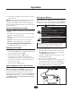
Operation GROUNDING THE GENERATOR OPERATING THE GENERATOR CAUTION The National Electrical Code requires that the frame and external electrically conductive parts of this generator be properly connected to an approved earth ground. Local electrical codes may also require proper grounding of the unit. For that purpose, a GROUNDING FASTENER is provided on the generator end (Figure 2). Exceeding generator’s wattage/amperage capacity can damage generator and/or electrical devices connected to it.
Operation 4. Charging a Battery Start engine according to instructions given in engine owner’s manual. Your generator has the capability of recharging a discharged 12 Volt automotive or utility style storage battery. DO NOT use the unit to charge any 6 Volt batteries. DO NOT use the unit to crank an engine having a discharged battery.
Operation 6. Connect battery charge cable clamp with black handle to the negative (–) battery terminal (Figure 5). 7. Start engine. Let engine run while battery recharges. 8. When battery has charged, shut down engine Figure 6 — Permanent Cold Weather Shelter Wind NOTE: Use an automotive hydrometer to test battery state of charge and condition. Follow the hydrometer manufacturer’s instructions carefully.
Operation RECEPTACLES 120 Volt AC, 20 Amp, GFCI Duplex Receptacles CAUTION Each duplex receptacle (Figure 8) is protected against overload by a push–to–reset circuit breaker. Receptacles may be marked with rating value greater than generator output capacity. Figure 8 — 120 Volt, 20 Amp GFCI Duplex Receptacle • NEVER attempt to power a device requiring more amperage than generator or receptacle can supply. • DO NOT overload the generator. See “Don’t Overload Generator”.
Operation Ground Fault Protection Testing the GFCI This unit is equipped with a Ground Fault Circuit Interrupter (GFCI).This device meets applicable federal, state and local codes. Test your GFCI outlet every month and before use, as follows: • Push the black “Test” button.The red “Reset” button should pop out, which should allow no power to reach the outlet. Use a test lamp in each outlet to test this.
Operation DON'T OVERLOAD GENERATOR 4. Plug in and turn on the next load. 5. Again, permit the generator to stabilize. 6. Repeat steps 4 and 5 for each additional load. NEVER add more loads than the generator capacity.Take special care to consider surge loads in generator capacity, as described above. Capacity You must make sure your generator can supply enough rated (running) and surge (starting) watts for the items you will power at the same time. Follow these simple steps: 1.
Maintenance SPECIFICATIONS NOTE: DO NOT use a garden hose to clean generator. Water can enter engine fuel system and cause problems. In addition, if water enters generator through cooling air slots, some of the water will be retained in voids and cracks of the rotor and stator winding insulation.Water and dirt buildup on the generator internal windings will eventually decrease the insulation resistance of these windings. Maximum Surge Watts . . . . . . . . . . . . . . . . .
Storage STORAGE Engine Storage See engine owner’s manual for instructions. The generator should be started at least once every seven days and allowed to run at least 30 minutes. If this cannot be done and you must store the unit for more than 30 days, use the following guidelines to prepare it for storage. Other Storage Tips • To prevent gum from forming in fuel system or on essential carburetor parts, add fuel stabilizer into fuel tank and fill with fresh fuel.
Notes NOTES 16
Troubleshooting TROUBLESHOOTING Problem Engine is running, but no AC output is available. Engine runs good but bogs down when loads are connected. Cause Solution 1. Circuit breaker is open. 1. Reset circuit breaker. 2. Poor connection or defective cord set. 2. Check and repair. 3. Connected device is bad. 3. Connect another device that is in good condition. 4. Fault in generator. 4. Contact local service facility. 1. Short circuit in a connected load. 1.
Schematic SCHEMATIC 18
Wiring Diagram WIRING DIAGRAM 19
Exploded Views EXPLODED VIEW – MAIN UNIT 41 20
Exploded Views PARTS LIST – MAIN UNIT Item Part # 1 N192958AGS 2 82857GS 3 N92531GS 4 190220GS 5 45771GS 6 NSP 7 N92731GS 8 96796GS 9 92609GS 10 190274BGS 11 187365JGS 12 189160GS 13 22142GS 14 193048GS 15 23762GS 16 66476GS 17 192569GS 18 31579GS 19 83083GS 20 B4986GS 21 67989GS 22 192981GS 23 193058GS 24 192983GS 25 193157GS 26 74908GS 27 193049GS 28 191435GS 29 86292GS 30 22531GS 31 191436GS 32 43107GS Description CRADLE MOUNT,Vibration SUPPORT, Engine HOUSING, Engine Adapter NUT ASSY, Alternator (see
Exploded Views EXPLODED VIEW AND PARTS LIST – ALTERNATOR Item Part # 1 186059GS 2 192919GS 3 192920AGS 4 193336GS 5 86308HGS 6 66386GS 7 66849GS 8 22694GS 9 81917GS 10 191051AGS 12 23762GS 13 192403XGS 14 189769GS 15 65795GS 16 66849AGS Description ADAPTER, Mounting, Alternator ROTOR STATOR RBC, (with O-Ring, p/n 189197GS) SCREW ASSY, Holder, Brush SCREW RECEPTACLE, 6 pin PIN, Roll ASSY,Wire, Ground WASHER WIRE, Ground REGULATOR,Voltage, AVR RECTIFIER SCREW 22
Exploded Views EXPLODED VIEW AND PARTS LIST – CONTROL PANEL Item Part # 1 B191714GS 2 B192836GS 3 23897GS 4 49226GS 5 91526GS 6 22447GS 7 82538GS 8 90418GS 9 77604GS 10 43182GS 11 51714GS 12 43181GS 13 22694GS 14 87962GS 15 84028GS Item Part # 16 64525GS 17 189367GS 18 64526GS 19 193077GS 20 22264GS 21 75477GS 22 51715GS 23 43180GS 24 75207GS 25 23365GS 26 75207PGS 27 193095GS 28 43437GS 29 80409GS 30 189502GS Description PANEL, Control BOX, Control Panel WASHER WASHER, Lock SCREW WASHER SWITCH, Rocker
Exploded Views EXPLODED VIEW AND PARTS LIST – WHEEL KIT Item Part # 1 22247GS 2 B4966GS 3 191267KGS 4 191265GS 5 39253GS 6 B89595GS 7 87841GS 8 22287GS 9 67989GS 10 B2071GS 11 B4605GS 12 B187113GS 13 39287GS 14 22145GS 15 49820GS 16 187104GS 17 B4135GS Description WASHER WHEEL AXLE E-RING SCREW BRACKET, Support, Unit MOUNT,Vibe Donut Type SCREW NUT NUT, Lock GRIP, Handle ASSY, Handle (Includes Item 11) SCREW WASHER NUT, Nylok WASHER, Nylon PIN, with Lanyard 24
LIMITED WARRANTY “Briggs & Stratton Power Products will repair or replace, free of charge, any part or parts of this Husqvarna® branded product** that are defective in material or workmanship or both.Transportation charges on parts submitted for repair or replacement under this warranty must be borne by purchaser.This warranty is effective for the time periods and subject to the conditions stated below. For warranty service, find the nearest Authorized Service Dealer by calling 1-877-224-0458.