
Manual


medicalattention.Ananti-vibrationsystem
doesnotguaranteetheavoidanceofthese
problems.Userswhooperatepowertoolson
acontinualandregularbasismustmonitor
closelytheirphysicalconditionandthe
conditionofthistool.
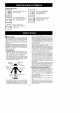
SPECIALNOTICE: Your saw is equipped
with a temperature limiting muffler and spark
arresting screen which meets the
requirements of California Codes 4442 and
4443. All U.S. forest land and the states of
California, Idaho, Mah_e, Mh_nesota, New
Jersey, Oregon, and Washington require by
law that many internal combustion engines
to be equipped with a spark arresting screen.
If you operate a chain saw in a state or locale
where such regulations exist, you are legally
responsible for maintaining the operating
condition of these parts. Failure to do so is
a violation of the law. Refer to the SERVICE
section for maintenance of the spark
arresting screen.
Failure to follow all Safety Rutes and
Precautions can result in serious injury. If
situations occur which are not covered in this
manual, use care and good judgement. If you
need assistance, contact your authorized
Husqvarna service dealer.
STANDARDS: This saw is listed by
Underwriter's Laboratories, Inc., in
accordance with:
ANSI B175.1-2000 American National
Standards for Gasoline-Powered Chain
Saws - Safety Requirements
CBA Z62.1-1995 Chah_ Saws
Occupational Health and Safety
CSA Z62.3=1gg6 Chain Saw Kickback
Occupational Health and Safety
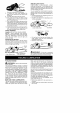
Protective gloves (not provided) should be
worn during assembly.
ATTACHING THE BAR & CHAIN (If
not already attached)
,_i_WARNING: Recheck each assem-
bly step if the saw is received assembled. Al-
ways wear gloves when handling the chain.
The chain is sharp and can cut you even
when it is not moving!
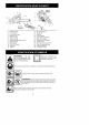
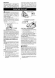
1. Loosen and remove the chain brake nuts
and the chain brake from the saw.
2. Remove the plastic shipping spacer (if
present).
Location of shipping spacer
Chain Brake
_o
Chain Brake
Nuts
Bar Tool
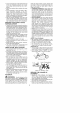
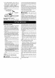
3. An adjusting pin and screw is used to ad-
just the tension of the chain. It is very im-
portant when assembling the bar. that
the pin tocated on the adjusting screw
aligns into a hole in the bar. Turning the
screw will move the adjustment pin up
and down the screw. Locate this adjust-
ment before you begin mounting the bar
onto the saw. See illustration.
Inside view of
._._C hai n Brake
ft _ _ '\
Adjustment located on Chain Brake
4. Turn the adjusting screw by hand coun-
terctockwise until the adjusting pin just
touches the stop. This should allow the
pin to be near the correct position. Fur-
ther adjustment may be necessary as
you mount the bar.
5. Slide guide bar behind clutch drum until
guide bar stops against clutch drum
sprocket.
Mount the Bar
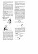
6. Prepare the chain by checking the proper
direction. Without following the illustration it
is easy to place the chain on the saw in the
wrong direction. Use the illustration of the
chain to determine the proper direction.
_ ip of
Bar
DIIRECTION OF ROTATION
Cutters Depth Gauge
Drive Links /
7. Place chain over and behind clutch, fit-
ting the drive links in the clutch drum
sprocket.