Rider 14 Pro Operator´s manual Please read these instructions carefully and make sure you understand them before using the machine.
Svenska – Sve-5 225/232/235 Bruk 31 97-11-25, 08.
CONTENTS Operator’s Manual for Rider 14 Pro Safety instructions .............................................. 2 Safety rules for USA ........................................ 2 Explanation of symbols ...................................... 4 Safety instructions .............................................. 5 General use ..................................................... 5 Driving on slopes ............................................. 6 Children ..........................................................
SAFETY INSTRUCTIONS ! 1. Safety rules for USA ! Safe operation practices for ride-on mowers IMPORTANT! This cutting machine is capable of amputating hands and feet and throwing objects. Failure to observe the following safety instructions could result in serious injury or death. I. General operation 1. Read, understand and follow all instructions in the manual and on the machine before starting. 2. Only allow responsible adults, who are familiar with the instructions, to operate the machine. 3.
SAFETY INSTRUCTIONS IV. Service 1. Use extra care in handling gasoline and other fuels. They are flammable and vapours are explosive. a) Use only an approved container. b) Never remove gas cap or add fuel with the engine running. Allow engine to cool before refuelling. Do not smoke. c) Never refuel the machine indoors. d) Never store the machine or fuel container inside where there is an open flame, such as in a water heater. 2. Never run a machine inside a closed area. 3.
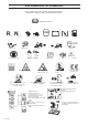
EXPLANATION OF SYMBOLS These symbols are on the machine and in the instructions. Study them carefully so that you know what they mean. Read the instructions.
SAFETY INSTRUCTIONS These instructions are for your safety. Read them carefully. ! This symbol implies that important safety rules are applicable. This is for your safety and the operating reliability of the machine. General use: • Make yourself familiar with the controls and how to stop quickly. • Read all the instructions in Operator’s Manual and on the machine before starting it. Make sure you understand them, and then follow them. • Only allow adults who are familiar with the machine to use it.
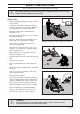
SAFETY INSTRUCTIONS • Watch out for traffic when working close to a road, or crossing one. • • Be careful when rounding a fixed object so that the blades do not hit it. Never drive intentionally over a foreign object. Do not cut close to edges, ditches or banks. The machine can suddenly tip over if a wheel goes over the edge of a drop or a ditch, or if a bank gives way. • Do not cut wet grass. It is slippery and the tyres can loose their grip so that the machine slides.
SAFETY INSTRUCTIONS Children Tragic accidents can occur if the driver does not pay attention to children in the vicinity. Children are often attracted to the machine and the work of mowing. Never assume that children stay where you last saw them. • Keep children away from the mowing area and under the close supervision of another adult. • Be on your guard and switch off the machine if children come into the work area. • Before and during reversing look behind and down for small children.
SAFETY INSTRUCTIONS • Be careful with the maintenance of the battery. Explosive gas is formed in the battery. Never handle the battery when smoking or in the vicinity of naked flames or sparks. Otherwise the battery can explode and cause severe injuries. • Never drive the machine in an enclosed space. The exhaust fumes contain carbon monoxide, an odourless, toxic and fatal gas.
PRESENTATION Presentation Congratulations on choosing an excellent quality product, Rider ProFlex. These instructions describe the Rider 14 Pro. The power transmission from the engine is handled by a hydrostatic gearbox, which enables variable speed by using the pedals. The Rider 14 Pro is equipped with a 14 horsepower Vanguard V-Twin engine from Briggs & Stratton. One pedal for driving forward and one for reverse. 7 6 5 4 3 2 1 8 9 8 9 10 11 12 13 14 Location of the controls 1.
PRESENTATION Throttle control The throttle control regulates the engine speed, and thereby also the rotation speed of the blades. To increase or reduce the engine speed the control is moved forwards or backwards. Choke lever The choke lever is used for cold starting and to give the engine a richer fuel mixture. For cold starting the lever is moved backwards to its end position. Speed limiter The speed of the machine is steplessly regulated with two pedals.
PRESENTATION Cutting unit Rider 14 Pro can be equipped with numerous attachments. The BioClip unit finely cuts the lawn by cutting the grass several times before returning the clippings to the lawn as fertiliser. The cutting unit with side or rear ejection, that is, the clippings are ejected to the side or behind the unit. Lift lever for cutting unit The lift lever is used to set the cutting unit in transport or mowing position. 1. Pull back the lever to the locked position for transport.
PRESENTATION Lever for adjustment of the cutting height The cutting height can be adjusted to 9 different positions with the cutting height lever. Cutting unit with side/rear ejector, BioClip cutting unit, 40-90 mm. 45-95 mm. Parking brake The parking brake is applied as follows: 2 1. Push down the brake pedal (1). 2. Push in the lock button on the steering column (2). 3. Release the brake pedal while holding the button pressed.
DRIVING Before starting • Read the safety instructions and information on the location and function of the controls before starting (see pages 5–12). • Conduct daily maintenance before starting (see maintenance schedule on page 17). • Adjust the seat to the required position. Starting the engine 1. Lift up the cutting unit by pulling the lever backwards to locked position (transport position) and apply the parking brake. 2. Move the throttle control to the middle position. 3.
DRIVING 5. When the engine starts release the ignition key immediately back to neutral position. IMPORTANT INFORMATION Do not run the starter for more than about 5 seconds at a time. If the engine does not start, wait about 10 seconds before trying again. 6. Push the choke lever gradually forward when the engine has started. 7. Set the required engine speed with the throttle control. ! WARNING! Never run the engine indoors, in enclosed or poorly ventilated areas.
DRIVING 3. Push in the lock button on the lift lever and lower down the cutting unit. 4. Select the required cutting height (1–9) with the cutting height lever. Cutting tips • Localise and mark stones and other fixed objects to avoid collision. • Start with a high cutting height and reduce down until the required mowing results are obtained. • • The mowing results are best with a high engine speed (fast rotating blades) and low driving speed (slow moving machine).
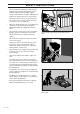
DRIVING ! WARNING! Never drive the machine on ground at an angle of more than 15°. Mow slopes upwards and downwards, never across. Avoid sudden changes in direction. MAX 15 Stopping the engine Preferably allow the engine to idle for a minute to obtain normal working temperature before stopping it if it has been working hard. 1. Lift up the cutting unit by pulling the lever back to the locked position. 2. Move the throttle control to the MIN. position. Turn the ignition key to the STOP.
MAINTENANCE Maintenance schedule The following is a list of the maintenance which should be conducted on the machine. For the items which are not described in these instructions go to an authorised service workshop.
MAINTENANCE Removing of the machine hoods Engine hood Release the two rubber straps on the rear edge of the engine hood and lift off the hood. Front hood Release the clip on the front hood and lift off the fender. Right-hand fender Dismantle the foot-plate (1), screws (2 and 3), and lift off the fender. 3 1 11 Left-hand fender Dismantle the screws (1 and 2), and lift off the fender.
MAINTENANCE Check the engine’s oil level Check the oil level in the engine when the machine is horizontal. Dismantle the engine hood as per the description on page 18. Take out the dip stick, wipe off the oil, and insert again. The dip stick must be fully screwed down. Now take out the dip stick again and check the oil level. The oil level should lie between the markings on dip stick. If the level approaches the ADD mark, top up with oil to the FULL mark on the dip stick.
MAINTENANCE Check the transmission’s air intake Check that the transmission’s air intake in not blocked. Check the transmission’s oil level 1. Check the transmission’s oil level by looking through the mesh on the air intake. The oil level should lie between the MIN and MAX markings on the oil canister at 20° C. If oil needs to be added the transmission cover must be dismantled first. Release the two screws (one on each side) and then lift off the transmission cover. 2.
MAINTENANCE Checking and adjustment of the steering wires The steering is controlled by means of wires. These can in time become slack, which implies that the adjustment of the steering becomes altered. Check and adjust the steering as follows: 1. Dismantle the frame-plate by releasing the screws (two on each side). 2. Check the tension of the steering wires by pushing them together (at the arrows).
MAINTENANCE Adjusting the brakes The brakes are adjusted as follows: 1. Loosen the lock nuts (1). 2. Adjust the wire using the adjuster screw (2) until the play on the wire is taken up. 3. Tighten the lock nuts (1). ! WARNING! Poorly adjusted brakes can result in reduced braking power. Check the level of the battery acid Check that the level of the battery acid lies between the markings. Top up the cells with distilled water only.
MAINTENANCE Replacing the air filter If the engine seems to lack power or does not run smoothly this may be because the air filter is clogged. It is therefore important to replace the air filter at regular intervals (see maintenance schedule on page 17 for correct service interval). The air filter is replaced as follows: 1. Dismantle the engine hood as described on page 18. 2. Fold out the two snap-locks and lift off the cover on the air filter housing. 3.
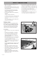
MAINTENANCE Fitting the cutting unit 1. Position the Rider on a flat surface and apply the parking brake, see page 10. Check that the lever for adjusting the cutting height is at the lowest setting. Make sure the support wheels are fitted to the cutting unit (1). 3 2. Grasp the handle at the front (BioClip 90) or hold the frame of the cutting unit (2) and slide the unit underneath the rider mower, making sure that the tongue on the cutting unit (3) engages correctly. 1 2 3.
MAINTENANCE Installing BioClip 90 In order to install BioClip 90 the drive belt support wheel must first be removed. 1 1. Disengage the spring from the tensioning wheel. 3. Remove the locking pin (1) that is located next to the support wheel. 2 8 9 4. Fit the cutting unit as instructed on the previous page. Checking and adjustment of the cutting unit’s ground pressure To achieve the best cutting results the cutting unit should follow the underlying surface without pressing too hard against it.
MAINTENANCE Checking the cutting unit’s parallelism Check the parallelism of the cutting unit as follows: 1. Place the machine on a level surface. 2. Measure the distance between the ground and the front and rear edges of the cutting unit hood. The cutting unit should slope forwards slightly so that the rear edge is 2-4 mm higher than the front edge. Adjusting the parallelism of the cutting unit 1. Remove the front hood and right-hand fender, as described on page 18. 2. Undo the nuts on the lift strut. 3.
MAINTENANCE Removing the cutting unit 1. Apply the parking brake, see page 10. 2. Adjust the cutting height to its lowest setting. 3. Remove the front hood, as described on page 18. 4. Fit the support wheels. ! WARNING! Wear protective glasses when removing the cutting unit. The spring which tensions up the belt can go off and cause personal injury. 5. Relieve the tensioning wheel by disconnecting the spring. 6. Lift the drive belt off the cutting unit drive pulley. 7. Pull out the pin.
MAINTENANCE 8. Place one foot on the front edge of the cutting unit. Raise the front edge of the unit slightly and unhook the height adjustment strut. 9. Remove the bolt and pull out the cutting unit. Removing the belt Starting point when Removing the belt: • No unit attached to the Rider. • The front part of the belt hangs loose. 8 9 The entire belt is only dismantled as set out below, when the snow plough is fitted on the Rider. • Remove the guide plate from underneath the drive wheel.
MAINTENANCE Replacing the cutting unit’s belts Belt replacement on the BioClip 103 Two transmission belts that synchronise the rotation of the blades power a BioClip 103. The belts are located under a hood on the cutting unit. 1. Remove the cutting unit, see page 25. 2. Remove the front bolt from the parallel strut and tip the strut backwards. Push the height adjustment strut forwards. 3. Loosen the two bolts holding the protective hood and then lift off the hood. BioClip 103 4.
MAINTENANCE 5. Assembly: First fit the lower belt and then the upper belt. Ensure the blades are positioned as set out in the diagram, at 90 degrees to each other, otherwise the belts must be adjusted. When the blade bearings are loose the belts can be moved around to the next tooth. Tighten the nuts enough so that the bearings rest against the cutting hood but still can be moved. Tension the belt by turning the eccentric adjuster on top of the cutting hood. Tighten the nut.
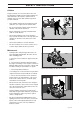
MAINTENANCE Service position for cutting unit The cutting head can be placed in the service position to provide easy access for cleaning, repairs and servicing. In the service position the cutting unit is raised and locked in the vertical position. Placing in service position P 1 1. Position the machine on flat ground. Apply the parking brake (1), see page 8. Adjust the cutting unit to the lowest cutting height and lower the cutting unit. 2. Remove the front hood by removing the pin.
MAINTENANCE 4. Fit the support wheels on either side of the rear of the cutting unit. 5. Disengage the spring from the drive belt tensioning wheel. 6. Place a foot on the front edge of the cutting unit near the wheel and raise the front edge of the unit to make it easier to remove the lift strut. Engage the strut in the holder.
MAINTENANCE 7. Lift off the drive belt (1). Then pull out the pin (2). 1 Take care not to get your hand trapped. 2 8. Pull the frame forwards and insert the pin. 9. Grasp the front edge of the cutting unit, pull out and raise into the service position. Restoring from service position To restore the machine from the service position, reverse the sequence “Placing in Service position“.
MAINTENANCE Checking the blades To achieve the best mowing results it is important that the blades are undamaged and well-sharpened. Check that the blades’ attachment screws are tight. IMPORTANT INFORMATION IMPORTANT INFORMATION On the Bioclip unit the relative positioning of the blades should always be as shown in the diagram with an angle of 90° between the blades. Otherwise the blades can go against each other and damage the unit.
MAINTENANCE Changing the oil The oil should be changed for the first time after 8 hours of running time. Thereafter it should be changed every 50 hours of running time. If the engine is run hard or during high temperatures the oil should be changed every 25 running hours. ! WARNING! Engine oil can be very hot if it is drained off directly after the engine is stopped. Therefore allow the engine to cool down first. 1. Dismantle the engine hood as described on page 18. 2.
MAINTENANCE Replacement of the oil filter 1. Dismantle the engine hood as described on page 18. 2. Drain off the engine oil according to the work description “Changing of engine oil” on page 34. 3. Dismantle the oil filter. If necessary use a filter extractor. 4. Apply new, clean engine oil on the seal for the new filter. 5. Fit the filter and tighten by hand. 6. Run the engine warm and check that there is no leakage round the oil filter seal.
MAINTENANCE Checking and adjustment of the throttle wire Check that the engine responds to the throttle control and that the correct engine speed is achieved at full throttle. If in doubt, contact the service workshop If necessary the following adjustment can be made: 1. Release the clamping screw and push the throttle control to full throttle position. 2. Pull the throttle wire’s outer casing to the right and tighten the clamping screw. Checking the tyre pressure The tyre pressure should be 60 kPa (0.
MAINTENANCE Replacement of the fuel filter Replace the fuel filter every 100 running hours (once per season) or more frequently if it is clogged. Replace the filter as follows: 1. Dismantle the engine hood as described on page 18. 2. Move the hose clips away from the filter. Use a pair of flat pliers. 3. Pull off the filter from the hose ends. 4. Press in the new filter on the hose ends. If necessary soap solution can be applied on the filter ends to simplify fitting. 5.
TROUBLE SHOOTING SCHEDULE Problem Procedure Engine will not start. • • • • Fuel tank empty. Plugs defective. Plug connections defective. Dirt in carburettor or fuel pipe. Starter does not pull round engine. • • • • • • Battery flat. Bad contact between cables and battery terminals. Lift lever for cutting unit in wrong position. Main fuse blown. The fuse is located in front of the battery under the battery cover. Ignition lock faulty. Gear shift/hydrostat pedal not in neutral.
STORAGE Winter storage At the end of the season the machine should immediately be put in order for storage, also if it is going to stand idle for more than 30 days. Fuel which is left to stand for long periods (30 days or more) can leave tacky deposits which can block the carburettor and interfere with the engine. Fuel stabiliser is an acceptable alternative to avoid tacky deposits during storage. If alkylate petrol (Aspen) is used stabiliser is not necessary since this fuel is stable.
WIRING DIAGRAM 1. 2. 3. 4. 5. 6. 7. Brake switch, hydrostat Microswitch, cutting unit Microswitch, seat Ignition lock Counter Start relay Engine Explanation of colour abbreviations in wiring diagram.
TECHNICAL DATA Rider 14 Pro Dimensions Rider 14 Pro Length without unit Width without unit Height Unladen weight Wheel base Track Tyre size Tyre pressure, front & rear Max. gradient 2 145 mm 1 050 mm 1 060 mm 245 kg 855 mm 715 mm 16 x 6,50 x 8 60 kPa (0,6 kp/cm2) 15° Engine Manufacture Power Displacement Fuel Tank volume Oil Oljevolym Oil volume incl.
TECHNICAL DATA Cutting unit Cutting width Cutting heights Blade length Sound level Cutting width Cutting heights Blade length Sound level BioClip 90 BioClip 103 900 mm 9 settings, 45-95 mm 440 mm 100 dB(A) 1030 mm 9 settings, 45-95 mm 410 mm 100 dB(A) Side ejector 97 Rear ejector 97 970 mm 9 settings, 40-80 mm 350 mm 100 dB(A) 970 mm 9 settings, 40-80 mm 350 mm 100 dB(A) We reserve the right to change technical specifications without prior notice.
NOTES 44 – English ´*3%[¶5ƨ
English – 45
´*3%[¶5ƨ 2000W02