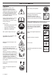
KEY TO SYMBOLS Symbols WARNING! A clearing saw, brushcutter or trimmer can be dangerous if used incorrectly or carelessly, and can cause serious or fatal injury to the operator or others. It is extremely important that you read and understand the contents of this operator’s manual. Wear sturdy, non-slip boots. Noise emission to the environment according to the European Community’s Directive. The machine’s emission is specified in chapter Technical data and on label.
CONTENTS Contents KEY TO SYMBOLS Symbols ................................................................ CONTENTS Contents ............................................................... Note the following before starting: ........................ INTRODUCTION Dear Customer, .................................................... WHAT IS WHAT? What is what on the brushcutter? ......................... GENERAL SAFETY PRECAUTIONS Impor tant ..............................................................
INTRODUCTION Dear Customer, Congratulations on your choice to buy a Husqvarna product! Husqvarna is based on a tradition that dates back to 1689, when the Swedish King Karl XI ordered the construction of a factory on the banks of the Husqvarna River, for production of muskets. The location was logical, since water power was harnessed from the Huskvarna River to create the waterpowered plant.
WHAT IS WHAT? 1 4 7 3 9 8 6 22 10 17 5 30 15 11 16 18 12 19 29 28 20 25 14 2 13 1 24 23 21 26 27 32 4 31 What is what on the brushcutter? 1 Blade (Not all markets) 17 Clutch cover 2 2-teeth blade (Not all markets) 18 Locking nut 3 Grease filler cap, bevel gear 19 Support flange 4 Bevel gear 20 Support cup 5 Cutting attachment guard 21 Drive disc 6 Shaft 22 Handlebar clamp 7 Start throttle / Stop switch 23 Operator′s manual 8 Throttle control 24 Transport guard 9
GENERAL SAFETY PRECAUTIONS Important Personal protective equipment IMPORTANT! IMPORTANT! The machine is only designed for trimming grass. A clearing saw, brushcutter or trimmer can be dangerous if used incorrectly or carelessly, and can cause serious or fatal injury to the operator or others. It is extremely important that you read and understand the contents of this operator’s manual.
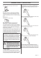
GENERAL SAFETY PRECAUTIONS BOOTS Wear boots with steel toe-caps and non-slip sole. control and the throttle lockout both move back to their original positions. This movement is controlled by two independent return springs. This arrangement means that the throttle control is automatically locked at the idle setting. CLOTHING Wear clothes made of a strong fabric and avoid loose clothing that can catch on twigs and branches. Always wear heavy, long pants. Do not wear jewellery, shorts sandals or go barefoot.
GENERAL SAFETY PRECAUTIONS be checked. See instructions under the heading Maintenance. Always use the recommended guard for the cutting attachment you are using. See chapter on Technical data. ! WARNING! Never use a cutting attachment without an approved guard. See the chapter on Technical data. If an incorrect or faulty guard is fitted this can cause serious personal injury.
GENERAL SAFETY PRECAUTIONS Quick release There is an easily accessible, quick release fitted at the front as a safety precaution in case the engine catches fire, or in any other situation that requires you to free yourself from the machine and harness. See instructions under the heading Adjusting the harness and clearing saw. Regularly check that the muffler is securely attached to the machine. ! Check that the harness straps are correctly positioned.
GENERAL SAFETY PRECAUTIONS Cutting equipment General rules This section describes how to choose and maintain your cutting equipment in order to: • Reduce the risk of blade thrust. • Obtain maximum cutting performance. • Extend the life of cutting equipment. Only use cutting attachments with the guards we recommend! See the chapter on Technical data. IMPORTANT! Only use cutting attachments with the guards we recommend! See the chapter on Technical data.
GENERAL SAFETY PRECAUTIONS Trimmer head IMPORTANT! Always ensure the trimmer cord is wound tightly and evenly around the drum, otherwise the machine will generate harmful vibration. • Only use the recommended trimmer heads and trimmer cords. These have been tested by the manufacturer to suit a particular engine size. This is especially important when a fully automatic trimmer head is used. Only use the recommended cutting attachment. See the chapter on Technical data.
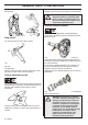
ASSEMBLY Fitting the main body labels. If they are moved outside of this area, it can cause the machine to be imbalanced, which can be dangerous. Connect the engine (A) to the tube (B) with four screws (C). A (A) Arrow labels Connecting throttle cable and stop switch wires Assembling the handlebar and throttle • • 1 Remove the air filter cover. 2 Insert the throttle cable (A) to the end of the adjuster (B).
ASSEMBLY and the cable position keep 1-2mm play between the cable lug and the slotted fitting when the throttle trigger is fully depressed. 10 Fit the dust cover (J). 1-2mm 7 When the throttle cable is adjusted correctly, tighten the lock-nut (F) and the M3 screw (G). 11 Refit the air filter cover. Fitting blades and trimmer heads ! 8 Plug the stop switch wires (H) into the matching connectors from the engine. Note that wire polarity is not important.
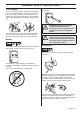
ASSEMBLY Fitting the guard extension CAUTION! The guard extension shall always be fitted when using the trimmer head/plastic blades and combination guard. The guard extension shall always be removed when using the grass blade and combination guard. • Fit the drive disc (B) on the output shaft. • Turn the blade shaft until one of the holes in the drive disc aligns with the corresponding hole in the gear housing. • Insert the locking pin (C) in the hole to lock the shaft.
ASSEMBLY • Insert the locking pin (C) in the hole to lock the shaft. • Screw on the trimmer head/plastic blades (H) in the opposite direction to the direction of rotation. Standard harness H Quick release H • At the front is an easily accessible, quick release. Use this if the engine catches fire or in any other emergency situation that requires you to free yourself from the machine and harness. To dismantle, follow the instructions in the reverse order.
FUEL HANDLING Fuel safety Petrol Never start the machine: 1 If you have spilt fuel on it. Wipe off the spillage and allow remaining fuel to evaporate. 2 If you have spilt fuel on yourself or your clothes, change your clothes. Wash any part of your body that has come in contact with fuel. Use soap and water. 3 If the machine is leaking fuel. Check regularly for leaks from the fuel cap and fuel lines.
FUEL HANDLING Mixing • Always mix the petrol and oil in a clean container intended for fuel. • Always start by filling half the amount of the petrol to be used. Then add the entire amount of oil. Mix (shake) the fuel mixture. Add the remaining amount of petrol. • Fuelling ! Mix (shake) the fuel mixture thoroughly before filling the machine’s fuel tank. WARNING! Taking the following precautions, will lessen the risk of fire: Do not smoke or place hot objects near fuel.
STARTING AND STOPPING Check before starting • Never use the machine without a guard nor with a defective guard. • All covers must be correctly fitted and undamaged before you start the machine. • Check the blade to ensure that no cracks have formed at the bottom of the teeth or by the centre hole. The most common reason why cracks are formed is that sharp corners have been formed at the bottom of the teeth while sharpening or that the blade has been used with dull teeth.
STARTING AND STOPPING Primer bulb: Press the air purge repeatedly until fuel begins to fill the bulb. The bulb need not be completely filled. shock if the spark plug cap has been damaged. Always use gloves. Do not use a machine with damaged spark plug cap. Choke: Set the choke control in the choke position. Stopping Stop the engine by switching off the ignition.
WORKING TECHNIQUES General working instructions 6 Always hold the machine with both hands. Hold the machine on the right side of your body. 7 Keep the cutting attachment below waist level. 8 Switch off the engine before moving to another area. Fit the transport guard before carrying or transporting the equipment any distance. 9 Never put the machine down with the engine running unless you have it in clear sight.
WORKING TECHNIQUES Basic working techniques • Always slow the engine to idle speed after each working operation. Long periods at full throttle without any load on the engine can lead to serious engine damage. Try to work rhythmically. Stand firmly with your feet apart. Move forward after the return stroke and stand firmly again. • Let the support cup rest lightly against the ground. It is used to protect the blade from hitting the ground.
WORKING TECHNIQUES Cutting • The trimmer is ideal for cutting grass that is difficult to reach using a normal lawn mower. Keep the cord parallel to the ground when cutting. Avoid pressing the trimmer head against the ground as this can ruin the lawn and damage the tool. • Do not allow the trimmer head to constantly come into contact with the ground during normal cutting. Constant contact of this type can cause damage and wear to the trimmer head.
MAINTENANCE Carburettor Adjusting the idle speed (T) Check that the air filter is clean. When the idle speed is correct, the cutting attachment should not rotate. If adjustment is required, close (turn clockwise) the idle adjustment screw T, with the engine running, until the cutting attachment starts to rotate. Open (turn anticlockwise) the screw until the cutting attachment stops.
MAINTENANCE Air filter Bevel gear The air filter must be regularly cleaned to remove dust and dirt in order to avoid: The bevel gear is filled with the right quantity of grease at the factory. However, before using the machine you should check that the bevel gear is filled three-quarters full with grease. Use HUSQVARNA special grease. • Carburettor malfunctions • Starting problems • Loss of engine power • Unnecessary wear to engine parts. • Excessive fuel consumption.
MAINTENANCE Maintenance schedule The following is a list of the maintenance that must be performed on the machine. Most of the items are described in the Maintenance section. The user must only carry out the maintenance and service work described in this Operator’s Manual. More extensive work must be carried out by an authorised service workshop. Maintenance Daily maintenance Clean the outside of the machine. X Check that the harness is not damaged.
TECHNICAL DATA Technical data Technical data 143R-II Engine Cylinder displacement, cm3 41,5 Cylinder bore, mm 40 Stroke, mm 33 Idle speed, rpm 2500 Recommended max. fast idle speed, rpm 12000 Speed of output shaft, rpm 9270 Max. engine output, acc.
TECHNICAL DATA Approved accessories Type Cutting attachment guard, Art. no.
S35 2 3 2,4-2,7 mm .095-.
S35 3 2 2,4-2,7 mm .095-.
T35, T35x 2 3 2,4-2,7 mm .095-.
T45, T45x 2 3 2,7-3,3 mm .106-.
T55x 1 2 A 3 B C A 2,7 - 4,0 mm / .105 - .160" B 8 m / 26’ C 15 cm / 5.
Trimmy SII 1 2,4-3,3 mm .095"-.