Operator’s Manual 14527E Gasoline containing up to 10% ethanol (E10) is acceptable for use in this machine. The use of any gasoline exceeding 10% ethanol (E10) will void the product warranty. 532 44 35-15 Please read the owner's manual carefully and make sure you understand the instructions before using the machine.
IMPORTANT Safe Operation Practices for Walk-Behind Snow Throwers This snow thrower is capable of amputating hands and feet and throwing objects. Failure to observe the following safety instructions could result in serious injury. WARNING: Snow throwers have exposed rotating parts, which can cause severe injury from contact, or from material thrown from the discharge chute. Keep the area of operation clear of all persons, small children and pets at all times including startup.
6. When cleaning, repairing or inspecting the snow thrower, stop the engine and make certain the collector/impeller and all moving parts have stopped. Disconnect the spark plug wire and keep the wire away from the plug to prevent someone from accidentally starting the engine. 7. Do not run the engine indoors, except when starting the engine and for transporting the snow thrower in or out of the building. Open the outside doors; exhaust fumes are dangerous. 8.
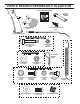
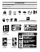
PARTS PACKED SEPARATELY IN CARTON (1) FUEL STABILIZER PACKET (1) MULTIWRENCH (180684) (1) POWER CORD (198563) SAFTEY IGNITION KEY (S) (193071) (1) AUGER CONTROL ROD (1) DISCHARGE CHUTE EXTRA SHEAR BOLTS AND NUTS (6) SHOULDER BOLT 1/4-20 x 1-3/4 (192090) (6) LOCKNUTS 1/4-20 (73800400) ROTATOR HEAD MOUNTING (3) RETAINER SPRINGS (169675) (1) WASHER 3/8 (19131316) (1) LOCKNUT 3/8 (73800600) CHUTE DEFLECTOR REMOTE CONTROL (1) LOCKNUT 5/16-18 (751153) (1) CARRIAGE BOLT 5/16-18 x 5/8 (72250505) (2) FL
ASSEMBLY / PRE-OPERATION Read these instructions and this manual in its entirety before you attempt to assemble or operate your new snow thrower. Reading the entire manual will familiarize you with the unit, which will assist you in assembly, operation and maintenance of the product. Your new snow thrower has been assembled at the factory with the exception of those parts left unassembled for shipping purposes. All parts such as nuts, washers, bolts, etc.
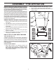
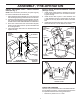
ASSEMBLY / PRE-OPERATION INSTALL TRACTION DRIVE CONTROL ROD (See Figs. 3 and 4) The traction drive control rod has the long loop on the end of the spring as shown. 1. Slide rubber sleeve up rod and hook end of spring into eye of cable with loop opening down as shown. 2. With top end of rod positioned under left side of control panel, push rod down and insert top end of rod into hole in drive control bracket. Secure with retainer spring. INSTALL AUGER CONTROL ROD (See Figs. 5 and 6) 1.
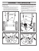
ASSEMBLY / PRE-OPERATION INSTALL CHUTE DEFLECTOR REMOTE CONTROL (See Figs. 8 and 9) 1. Install remote cable bracket to discharge chute with 5/16-18 carriage bolt and 5/16-18 locknut as shown. Tighten securely. 2. Install remote cable eyelet to chute deflector with 1/4-20 shoulder bolt and 1/4-20 locknut as shown. Tighten nut securely. Eyelet will be loose on shoulder bolt. 3. Install spring hooks between hex nuts on chute rotater head and into hole in chute deflector as shown.
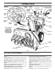
OPERATION KNOW YOUR SNOW THROWER READ THIS OWNER'S MANUAL AND ALL SAFETY RULES BEFORE OPERATING YOUR SNOW THROWER. Compare the illustrations with your snow thrower to familiarize yourself with the location of various controls and adjustments. Save this manual for future reference. These symbols may appear on your snow thrower or in literature supplied with the product. Learn and understand their meaning.
OPERATION GASOLINE FILLER CAP ELECTRIC START BUTTON MUFFLER AUGER CONTROL LEVER RECOIL (AUXILIARY) STARTER HANDLE DISCHARGE CHUTE CONTROL LEVER DRIVE SPEED CONTROL LEVER TRACTION DRIVE CONTROL LEVER CHUTE DEFLECTOR CHOKE CONTROL PRIMER SAFETY IGNITION KEY DEFLECTOR REMOTE CONTROL LEVER LH TURN TRIGGER FUEL SHUT-OFF VALVE DISCHARGE CHUTE LIGHT THROTTLE / ENGINE CONTROL HANDLE KNOB CLEAN-OUT TOOL NOTE: ITEMS ABOVE ARE SHOWN IN THEIR TYPICAL LOCATION ON THE ENGINE.
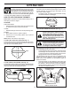
OPERATION The operation of any snow thrower can result in foreign objects thrown into the eyes, which can result in severe eye damage. Always wear safety glasses or eye shields while operating your snow thrower or performing any adjustments or repairs. We recommend standard safety glasses or a wide vision safety mask worn over spectacles. TO USE CHOKE CONTROL (See Fig. 13) The choke control is located on the engine. Use the choke control whenever you are starting a cold engine.
OPERATION TO THROW SNOW (See Fig. 15) The auger rotation is controlled by the auger control lever located on the right side handle. • Squeeze auger control lever to handle to engage the auger and throw snow. • Release the auger control lever to stop throwing snow. AUGER CONTROL LEVER • Squeeze traction drive control lever to handle to engage the drive system. • Release traction drive control lever to stop the forward or reverse movement of the snow thrower.
OPERATION TO ADJUST SKID PLATES (See Fig. 19) NOTE: The wrench provided in your parts bag may be used to adjust the skid plates. Skid plates are located on each side of the auger housing and adjust the clearance between the scraper bar and the ground surface. Adjust skid plates evenly to proper height for current surface conditions.
OPERATION CHOKE CONTROL ENGINE OIL FILL CAP / DIPSTICK Allow the engine to warm up for a few minutes. Engine will not develop full power until it has reached normal operating temperature. WARM START - ELECTRIC STARTER Follow the steps above, keeping the choke control in the “OFF” position. COLD START - RECOIL STARTER 1. Insert safety ignition key (Tied to recoil start cord) into ignition slot until it clicks. DO NOT turn the key. Keep the extra safety ignition key in a safe place. 2.
OPERATION SNOW THROWING TIPS • • • • • • • • • • • Always operate the snow thrower with the engine at full throttle. Full throttle offers the best performance. Go slower in deep, freezing or heavy wet snow. Use the drive speed control, NOT the throttle, to adjust speed. It is easier and more efficient to remove snow immediately after it falls. The best time to remove snow is the early morning. At this time the snow is usually dry and has not been exposed to the direct sun and warming temperatures.
MAINTENANCE GENERAL RECOMMENDATIONS LUBRICATION CHART The warranty on this snow thrower does not cover items that have been subjected to operator abuse or negligence. To receive full value from the warranty, operator must maintain snow thrower as instructed in this manual. Some adjustments will need to be made periodically to properly maintain your snow thrower. At least once a season, check to see if you should make any of the adjustments described in the Service and Adjustments section of this manual.
MAINTENANCE TO CHANGE ENGINE OIL Determine temperature range anticipated before next oil change. All oil must meet API service classification SG–SL. • Be sure snow thrower is on level surface. • Oil will drain more freely when warm. • Catch oil in a suitable container. NOTE: The left side wheel may be removed from snow thrower for easier access to the oil drain plug and placement of a suitable container.
SERVICE AND ADJUSTMENTS WARNING: To avoid serious injury, before performing any service or adjustments: 1. Be sure throttle is in STOP position. 2. Remove safety ignition key. 3. Make sure the augers and all moving parts have completely stopped. 4. Disconnect spark plug wire from spark plug and place wire where it cannot come in contact with plug. SNOW THROWER TO ADJUST SNOW THROWER HEIGHT See “TO ADJUST SKID PLATES” and “SCRAPER BAR” in the Operation section of this manual.
SERVICE AND ADJUSTMENTS TO REPLACE BELTS (See Fig. 24) The auger and traction drive belts are not adjustable. If the belts are damaged or begin to slip from wear, they should be replaced. It is recommended that the belt(s) be replaced by a service center/department. NOTE: It is recommended that both the auger and traction drive belt be replaced at the same time.
SERVICE AND ADJUSTMENTS ENGINE TO REMOVE WHEELS (See Fig. 25) • Remove the wheel pin and retainer pin and remove wheel from axle. NOTE: To seal punctures or prevent flat tires due to slow leaks, tire sealant may be purchased from your local parts dealer. Tire sealant also prevents tire dry rot and corrosion. WHEEL PIN (INSTALL IN OUTER HOLE OF AXLE ONLY) SEE ENGINE MANUAL. CARBURETOR Your carburetor is not adjustable. Engine performance should not be affected at altitudes up to 2,134 meters.
STORAGE ENGINE OIL Drain oil (with engine warm) and replace with clean engine oil. (See “ENGINE” in the Maintenance section of this manual). Immediately prepare your snow thrower for storage at the end of the season or if the unit will not be used for 30 days or more. WARNING: Never store the snow thrower with gasoline in the tank inside a building where fumes may reach an open flame, spark or pilot light as on a furnace, water heater, clothes dryer or gas appliance.
TROUBLESHOOTING See appropriate section in manual unless directed to an authorized service center/department. PROBLEM Does not start CAUSE 1. Fuel shut-off valve (if so equipped) in OFF position. 2. Safety ignition key is not inserted. 3. Out of fuel. 4. Throttle in STOP position (or ON/OFF switch is OFF). 5. Choke in OFF position. 6. Primer not depressed. 7. Engine is flooded. 8. Spark plug wire is disconnected. 9. Bad spark plug. 10. Stale fuel. 11. Water in fuel. CORRECTION 1.
&RQVXPHU :KHHOHG 3URGXFWV ± /LPLWHG :DUUDQW\ +XVTYDUQD ZDUUDQWV WR WKH RULJLQDO UHWDLO SXUFKDVHU WKDW WKLV +XVTYDUQD SURGXFW LV IUHH IURP GHIHFWV LQ PDWHULDO RU ZRUNPDQVKLS XQGHU QRUPDO XVH DQG PDLQWHQDQFH IURP WKH GDWH RI UHWDLO SXUFKDVH IRU WKH DSSOLFDEOH :DUUDQW\ 3HULRG VKRZQ RQ ([KLELW $ &HUWDLQ FRPSRQHQWV H J HQJLQHV DQG WUDQVPLVVLRQV DUH H[FOXGHG IURP FRYHUDJH DQG RWKHU OLPLWDWLRQV DSSO\ DV GHVFULEHG LQ WKLV GRFXPHQW +XVTYDUQD ZLOO UHSDLU RU UHSODFH DW LWV GLVFUHWLRQ DQ\ GHIHFWLYH SURG
F 3UHYHQWDWLYH PDLQWHQDQFH DV RXWOLQHG LQ WKH RSHUDWRU¶V PDQXDO ,Q DGGLWLRQ \RX PXVW FHDVH XVLQJ WKH SURGXFW LPPHGLDWHO\ XSRQ DQ\ IDLOXUH RU GDPDJH 7KH SURGXFW VKRXOG EH WDNHQ WR DQ DXWKRUL]HG +XVTYDUQD VHUYLFLQJ GHDOHU SULRU WR DQ\ IXUWKHU XVH 'DPDJHV UHVXOWLQJ IURP QRUPDO DJLQJ ZHDU DQG WHDU RU QHJOHFW DUH 127 FRYHUHG 7KH /LPLWHG :DUUDQW\ GRHV QRW FRYHU GDPDJH RWKHU WKDQ WKDW UHVXOWLQJ IURP GHIHFWV LQ PDWHULDO RU ZRUNPDQVKLS 7KH IROORZLQJ DUH 127 FRQVL
&RQVXPHU :KHHOHG :DUUDQW\ &KDUW ([KLELW $ &RQVXPHU SHUVRQDO KRXVHKROG XVH RQO\ 3URGXFW &RPSRQHQW 5LGLQJ /DZQ 7UDFWRUV )UDPH &KDVVLV )URQW $[OH (QJLQH 7UDQVPLVVLRQ LI PDGH E\ +XVTYDUQD 3HHUOHVV 7UDQVPLVVLRQ LI WKLUG SDUW\ %DWWHU\ 2WKHU 1RQ ([SHQGDEOH &RPSRQHQWV 5HVLGHQWLDO =HUR 7XUQ 0RZHUV 5= 2QO\ (QJLQH 7UDQVPLVVLRQ %DWWHU\ 2WKHU 1RQ ([SHQGDEOH &RPSRQHQWV 5HVLGHQWLDO =HUR 7XUQ 0RZHUV 0= (= (QJLQH 7UDQVPLVVLRQ %DWWHU\ 2WKHU 1RQ ([SHQGDEOH &RPSRQHQWV /( (GJHU (QJLQH
&RQVXPHU :KHHOHG :DUUDQW\ &KDUW ([KLELW $ &RQVXPHU SHUVRQDO KRXVHKROG XVH RQO\ &RPPHUFLDO DQ\ FRPPHUFLDO 5HQWDO DQ\ UHQWDO SURIHVVLRQDO LQVWLWXWLRQDO XVDJH DULJFXOXWUDO RU LQFRPH SURGXFLQJ XVH RWKHU WKDQ 5HQWDO 8VH 3URGXFW &RPSRQHQW )URQW 0RXQWHG 'HFN 5LGHUV (QJLQH 7UDQVPLVVLRQ
SERVICE NOTES 26
SERVICE NOTES 27
07/25/2011 TH