Operator′s manual Rider 15T Rider 15T AWD Rider 15Ts AWD Please read the operator’s manual carefully and make sure you understand the instructions before using the machine.
CONTENTS Contents CONTENTS Contents ...................................................................... Service journal Pre-delivery service ..................................................... After the first 8 hours ................................................... INTRODUCTION Dear Customer, ............................................................ Driving and transport on public roads .......................... Towing ..........................................................................
Service journal Pre-delivery service 1 Charge the battery for 4 hours at max. 3 amp. 2 Fit steering wheel, seat and any optional equipment. 3 Check and adjust tyre pressure (60 Kpa, 0.6 bar, 9 PSI). 4 Adjust cutting unit: Adjust lift springs (effective weight of cutting unit should be 12-15kg / 26.5-33 lb). Adjust cutting unit so that rear edge is about 2-4 mm / 1/8” higher than front edge.
INTRODUCTION Dear Customer, Thank you for choosing a Husqvarna Rider. Husqvarna Riders are built to a unique design with a front-mounted cutting unit and a patented rear-wheel steering system. Riders are designed for maximum efficiency even in small or confined areas. The closely grouped controls and pedal-operated hydrostatic transmission also contribute to the performance of this machine. We hope you will find this operator’s manual very useful.
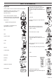
KEY TO SYMBOLS Symbols These symbols are on the machine and in the instructions. WARNING! Careless or incorrect use can result in serious or fatal injury to the operator or others. Noise emission to the environment according to the European Community’s Directive. The machine’s emission is specified in chapter Technical data and on label. Clutch in Please read the operator’s manual carefully and make sure you understand the instructions before using the machine.
KEY TO SYMBOLS Check the engine’s oil level Check transmission oil level Lift up the cutting unit Apply the parking brake.
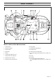
WHAT IS WHAT? What is what on the ride-on mower 1 Choke control 10 Parking brake 2 Switch for the lights 11 Lock button for parking brake 3 Throttle control 12 Seat adjustment.
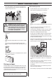
SAFETY INSTRUCTIONS Safety instructions These instructions are for your safety. Read them carefully. Insure your Rider • Stop the engine and prevent the engine from being started until you have cleaned the outlet channel. • Look out for the ejector and do not direct it towards anyone. • Stop the engine and prevent it from starting before you clean the cutting unit. • Check the insurance coverage for your new Rider. • Contact your insurance company.
SAFETY INSTRUCTIONS • Never allow children or other persons not trained in the use of the machine to use or service it. Local laws may regulate the age of the user. ! • WARNING! You must use approved personal protective equipment whenever you use the machine. Personal protective equipment cannot eliminate the risk of injury but it will reduce the degree of injury if an accident does happen. Ask your dealer for help in choosing the right equipment.
SAFETY INSTRUCTIONS • Follow the manufacturer’s recommendations regarding wheel weights or counterbalance weights to increase machine stability. IMPORTANT INFORMATION Wheel weights fitted on the rear wheels are recommended when driving on slopes for safer steering and improved manoeuvrability. Consult your dealer concerning the use of wheel weights if you are unsure. Wheel weights can not be used on AWD-machines. Use counterweights.
SAFETY INSTRUCTIONS • Do not change the setting of governors and avoid running the engine at excessively high revs. If you run too fast, you risk damaging the machine components. • Never use the machine indoors or in spaces lacking proper ventilation. Exhaust fumes contain carbon monoxide, an odourless, poisonous and highly dangerous gas. • Stop and inspect the equipment if you run over or into anything. If necessary, make repairs before starting. • Never make adjustments with the engine running.
PRESENTATION Presentation Choke control Congratulations on your choice of an excellent quality product that will give you great pleasure for many years. This operator’s manual describes Rider 15T, Rider 15Ts AWD and Rider 15T AWD. The choke lever is used for cold starting and to give the engine a richer fuel mixture. For cold starting the lever is moved backwards to its end position. The machines are equipped with chronometer and lights. Speed limiter Rider 15T AWD is equipped with all wheel drive.
PRESENTATION Cutting unit Cutting height adjustment lever Rider 15T, Rider 15T AWD and Rider 15Ts AWD can be equipped with three different cutting units. The cutting height can be adjusted to 7 different positions with the cutting height lever. 25-80 mm Lights • CombiClip 94 • CombiClip 103 • CombiClip 112 The lights are switched on and off using the power switch on the control panel. The Combi-unit, equipped with a BioClip-plug, finely chops the cuttings to fertiliser.
PRESENTATION To adjust move the lever under the front edge of the seat to the left, so that the seat can be moved forward or backwards to the required position. • Clutch control, rear axle - Control drawn out, drive system disengaged. Fuelling The engine runs on unleaded petrol with a minimum octane rating of 87 (not mixed with oil). We recommend the use of biodegradable alkylate petrol. (max. methanol 5%, max. ethanol 10%, max. MTBE 15%) - Control depressed, drive system engaged.
Driving Before starting • Read the safety instructions and information concerning the placement of controls and functions before starting. • Perform daily maintenance before starting as set out in the Maintenance schedule. 4 If the engine is cold move the choke lever backwards to its end position. 5 Turn the ignition key to the start position. 6 When the engine starts release the ignition key immediately back to neutral position.
Driving 8 Let the engine run at moderate speed or half throttle for 35 minutes before subjecting it to heavy load. • Connect each end of the red cable to the POSITIVE pole (+) on each battery, exercise care not to short circuit any of the ends against the chassis. • Connect one end of the black cable to the NEGATIVE pole (-) on the fully charged battery. • Connect the other end of the black cable to a good CHASSIS EARTH, away from the fuel tank and the battery.
Driving 4 Press in the lock button on the lifting lever and lower the cutting unit. • When the BioClip function is used, it is very important that the mowing interval is not too long. ! WARNING! Do not use the machine on ground that slopes more than 10°°. Mow slopes upwards and downwards, never across. Avoid sudden changes in direction. IMPORTANT INFORMATION The life span of the drive belts is increased significantly if the engine runs at a low speed when the blades are engaged.
Maintenance Maintenance schedule The following is a list of the maintenance which should be conducted on the machine. For those points not described in this manual, visit an authorised service workshop.
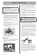
Maintenance Cleaning Front cover Clean the machine directly after use. It is much easier to wash off grass cuttings before they dry. Release the clip on the front hood and lift off the fender. Right-hand fender Oily dirt can be removed using a cold degreasing agent. Spray on a thin layer. Remove the accelerator knob (1), screws (2 and 3), and remove the cover. Rinse at normal water pressure. Do not direct the jet towards electrical components or bearings.
Maintenance 2 3 Check the tension of the steering wires by squeezing them together by the arrows as illustrated. It should be possible to push them together so that the distance between them is half as much, without using unnecessary force. Apply and lock the parking brake. When the machine does not stand still, the parking brake should be adjusted according to the following. 1 Remove the left-hand wing cover.
Maintenance Checking and adjusting the choke wire Replacing the air filter If the engine is producing black smoke or is difficult to start then the choke wire (upper wire) may be incorrectly adjusted. If doubts arise, contact your service representative. If it is necessary to adjust the choke, proceed as follows: ! WARNING! The exhaust system is hot. Let it cool before starting to replace the air filter.
Maintenance 6 If the paper filter is still dirty it should be replaced with a new one. 5 Reinsert the spark plug, turning by hand to avoid damaging the threads. Always replace the paper filter every 200 hours. 6 Tighten the spark plug, once it touches the seating, with the spark plug spanner. Tighten the spark plug so that the washer is compressed. A used spark plug should be turned 1/8 of a turn from the seated position. A new spark plug should be turned a 1/4 turn from the seated position.
Maintenance Check the safety system Start motor The machine is equipped with a safety system that prevents starting or driving under the following conditions. The engine should only be possible to start when the cutting unit is in its raised position and the hydrostat pedals are in the neutral position. The engine can not be started if the parking brake is not pressed down. Ignition system Works The driver does not need to be seated in the driver’s seat.
Maintenance Replacing the light bulbs 9 For information about the bulb type, see Technical Data. Main fuse 1 Loosen the lock nut and remove the Allen bolt. Remove the steering wheel. Replace the steering wheel. The main fuse is placed in a detachable holder under the battery case’s cover, in front of the battery. Type: Flat pin, 15 A. 2 3 Unscrew the two screws holding the cover on the power servo housing. One screw on each side. Do not use any other type of fuse when replacing.
Maintenance Open the engine cover. 4 Engage the belt in the belt holder. 5 Push the deck in and put the front guide plugs in the grooves on the equipment frame, one on each side. Check that the cooling intake is free from leaves, grass and dirt. Check the air duct, located on the inside of the engine cover, ensure it is clean and does not rub against the cooling air intake. A blocked cooling intake will interfere with the cooling of the engine, which can damage the engine.
Maintenance 9 Hook up the height adjustment strut. 4 Pull out the cutting unit. 10 Secure the collet spring. ! WARNING! Observe caution to avoid trapping your hand. Checking and adjustment of the cutting unit’s ground pressure 11 Fit the front cover. Removing the cutting unit ! 1 WARNING! Wear protective glasses when dismantling the cutting unit. The spring which tensions up the belt may break and cause personal injury.
Maintenance Checking the cutting unit’s parallelism Replacing the cutting unit belts Check the cutting unit’s parallelism as follows: 1 ! Check the air pressure in the tyres 60 kPa/0.6 kp/cm2/8.5 PSI. 2 Place the machine on a flat surface. 3 Put the lifting lever in the mowing position. 4 Measure the distance between the ground and the front and rear edges of the cutting unit hood. The cutting unit should have a slight slant, with the rear edge 2-4 mm (1/ 8”) higher than the front edge.
Maintenance 7 Remove the screws on the cutting cover. Lift the unit frame and remove the cutting unit cover. 8 Loosen the spring that tensions the V-belt and pry off the belt. 4 Disengage the spring for the drive belt tensioning wheel. 5 Loosen on the cutting height stay and place in the holder. ! Assemble the parts in the reverse order. Service position for the cutting unit WARNING! Observe caution to avoid trapping your hand. 6 Remove the drive belt and place it in the belt holder.
Maintenance Restoring from service position Removing the BioClip plug 1 Grip the front edge of the unit and loosen the lock, fold down and slide in the unit. 2 Replace the cutting height stay and the belt. To change a Combi unit from BioClip function to cutting unit with rear ejection, remove the BioClip plug located under the unit with three screws. CombiClip 103, CombiClip 112 3 4 1 Put the unit in the service position, see Placing in the service position.
Lubrication Checking the engine’s oil level. Replacing the engine oil Check the oil level in the engine when the Rider stands horizontal with the engine switched off. The engine oil should be changed the first time after 8 hours running time. It should then be changed after every 100 hours of running time. Open the engine cover. Loosen the dipstick, pull it up and wipe it off. When operating with a heavy load or at high ambient temperatures, replace every 50 hours.
Lubrication Lightly lubricate the rubber seal on the new oil filter using new oil. Fit the oil filter by turning clockwise. Turn by hand until the rubber seal is seated. Now tighten a further half turn. Fill with new oil according to Checking the engine’s oil level. Start the engine and let it idle for about 3 minutes. Now stop it and check for signs of leakage. Fill with oil to compensate for the oil held in the new oil filter. Checking the transmission oil level 1 Remove the transmission cover.
Troubleshooting schedule Problem Engine does not start Procedure There is no fuel in the fuel tank Spark plug defective Faulty spark plug connections or interchanged cables Dirt in the carburettor or fuel line Starter motor does not turn over the engine Starter motor does not turn over the engine Battery flat Bad contact between the cable and battery Lift lever for cutting unit in wrong position Main fuse blown. This fuse is in front of the battery, under the battery cover.
Storage Winter storage Service At the end of the season, or if the machine is going to stand idle for more than 30 days, it should immediately be made ready for storage. Fuel which is left to stand for long periods (30 days or more) can leave tacky deposits which can block the carburettor and interfere with the engine. Low season is the most suitable time to perform a service or overhaul of the machine in order to ensure high function safety during high season.
Technical data Dimensions Rider 15T Rider 15T AWD Rider 15Ts AWD Length without cutting unit, mm/ft 2020/6,61 2020/6,61 2020/6,61 Width without cutting unit, mm/ft 890/2,92 890/2,92 890/2,92 Height, mm/ft 1150/3,77 1150/3,77 1150/3,77 Operating weight with cutting deck, kg/ 275-283/606-624 294-302/648-666 307-315/679-694 lb Wheel base, mm/ft 887/2,91 887/2,91 887/2,91 Track width, front, mm/ft 712/2,34 712/2,34 712/2,34 Track width, rear, mm/ft 627/2,06 627/2,06 627/2,06 Tyre dimensions 16 x 6,50 x 8 16 x 6
Technical data Cutting unit CombiClip 94 CombiClip 103 CombiClip 112 Cutting width, mm/inch 940/37 1030 / 41 1120 / 44.1 Cutting heights, 7 positions, mm/inch 25-75/0.98-2.95 25-75/0.98-2.95 25-75/0.98-2.95 Blade length, mm/inch 358/14.09 388/15.28 420 / 16,5 IMPORTANT INFORMATION When the service life of this product has been served and it is no longer used it should be returned to the dealer or to an applicable station for recycling.
Technical data EC-declaration of conformity (Applies to Europe only) Husqvarna AB, SE-561 82 Huskvarna, Sweden, tel.
´®z+U+r¶6§¨ ´®z+U+r¶6§¨
Original instructions 1153118-26 ´®z+U+r¶6§¨ ´®z+U+r¶6§¨ 2010-03-24