Operator’s Manual 1650EXLT Gasoline containing up to 10% ethanol (E10) is acceptable for use in this machine. The use of any gasoline exceeding 10% ethanol (E10) will void the product warranty. 115 49 77-27 Rev. 1 Please read the owner's manual carefully and make sure you understand the instructions before using the machine.
IMPORTANT Safe Operation Practices for Walk-Behind Snow Throwers This snow thrower is capable of amputating hands and feet and throwing objects. Failure to observe the following safety instructions could result in serious injury. WARNING: Snow throwers have exposed rotating parts, which can cause severe injury from contact, or from material thrown from the discharge chute. Keep the area of operation clear of all persons, small children and pets at all times including startup.
Clearing a Clogged Discharge Chute 6. When cleaning, repairing or inspecting the snow thrower, stop the engine and make certain the collector/impeller and all moving parts have stopped. Disconnect the spark plug wire and keep the wire away from the plug to prevent someone from accidentally starting the engine. 7. Do not run the engine indoors, except when starting the engine and for transporting the snow thrower in or out of the building. Open the outside doors; exhaust fumes are dangerous. 8.
PRODUCT SPECIFICATIONS CONGRATULATIONS on your purchase of a new snow thrower. It has been designed, engineered and manufactured to give best possible dependability and performance. Should you experience any problem you cannot easily remedy, please contact your nearest authorized service center. We have competent, well-trained technicians and the proper tools to service or repair this unit. Please read and retain this manual.
PARTS PACKED SEPARATELY IN CARTON (1) MULTIWRENCH (180684) (1) POWER CORD (198563) SAFTEY IGNITION KEY (S) (193071) (1) AUGER CONTROL ROD (1) DISCHARGE CHUTE EXTRA SHEAR BOLTS AND NUTS (6) SHOULDER BOLT 1/4-20 x 1-3/4 (192090) (6) LOCKNUTS 1/4-20 (73800400) ROTATOR HEAD MOUNTING (3) RETAINER SPRINGS (169675) (1) WASHER 3/8 (19131316) (1) LOCKNUT 3/8 (73800600) CHUTE DEFLECTOR REMOTE CONTROL (1) LOCKNUT 5/16-18 (751153) (1) CARRIAGE BOLT 5/16-18 x 5/8 (72250505) (2) FLAT WASHERS (1) LOCKNUT 1/4
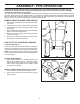
ASSEMBLY / PRE-OPERATION Read these instructions and this manual in its entirety before you attempt to assemble or operate your new snow thrower. Reading the entire manual will familiarize you with the unit, which will assist you in assembly, operation and maintenance of the product. Your new snow thrower has been assembled at the factory with the exception of those parts left unassembled for shipping purposes. All parts such as nuts, washers, bolts, etc.
ASSEMBLY / PRE-OPERATION INSTALL TRACTION DRIVE CONTROL ROD (See Figs. 3 and 4) The traction drive control rod is installed on the snow thrower. 1. Remove plastic tie securing rod to lower handle. 2. With top end of rod positioned under left side of control panel, push rod down and insert top end of rod into hole in drive control bracket. Secure with retainer spring. INSTALL AUGER CONTROL ROD (See Figs. 5 and 6) 1.
ASSEMBLY / PRE-OPERATION INSTALL DISCHARGE CHUTE / CHUTE ROTATOR HEAD (See Fig. 7) NOTE: The multi-wrench provided in your parts bag may be used to install the chute rotator head. 1. Place discharge chute assembly on top of chute base with discharge opening toward front of snow thrower. 2. Position chute rotator head over chute bracket. If necessary, rotate chute assembly to align square and pin on underside of chute rotator head with holes in chute bracket. 3.
OPERATION KNOW YOUR SNOW THROWER READ THIS OWNER'S MANUAL AND ALL SAFETY RULES BEFORE OPERATING YOUR SNOW THROWER. Compare the illustrations with your snow thrower to familiarize yourself with the location of various controls and adjustments. Save this manual for future reference. These symbols may appear on your snow thrower or in literature supplied with the product. Learn and understand their meaning.
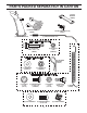
OPERATION GASOLINE FILLER CAP ELECTRIC START BUTTON DISCHARGE CHUTE CONTROL LEVER AUGER CONTROL DRIVE SPEED DEFLECTOR TRACTION LEVER CONTROL LEVER REMOTE DRIVE CONTROL LEVER CONTROL RECOIL (AUXILIARY) LEVER STARTER HANDLE MUFFLER CHOKE CONTROL CHUTE DEFLECTOR PRIMER SAFETY IGNITION KEY LH TURN TRIGGER FUEL SHUT-OFF VALVE LIGHT THROTTLE / ENGINE CONTROL HANDLE KNOB CLEAN-OUT TOOL NOTE: ITEMS ABOVE ARE SHOWN IN THEIR TYPICAL LOCATION ON THE ENGINE.
OPERATION To operate the height adjust mechanism, using your foot, push down on the pedal, tilt the unit to align the pins with the selected height position and slowly release foot pressure until the pins are seated in the desired height setting. TRANSPORT AND HEIGHT ADJUSTMENT OF SNOW THROWER TO TRANSPORT (See Figs. 11 & 12) When transporting your snowthrower, be sure to disengage the transmission by placing freewheel control into FREEWHEEL position (See Fig.
OPERATION TO USE FUEL SHUT-OFF VALVE (See Fig. 14) The fuel shut-off valve is located beneath the fuel tank on the engine. Always operate the snow thrower with the fuel shut-off valve in the OPEN position. WARNING: If the discharge chute or auger become clogged, shut-off engine and wait for all moving parts to stop. Use the clean-out tool, NOT YOUR HANDS, to unclog the chute and/or auger. The DIRECTION in which snow is to be thrown is controlled by the discharge chute control lever.
OPERATION NOTE: When both traction drive and auger control levers are engaged, the traction drive control lever will lock the auger control lever in the engaged position. This will allow you to release your right hand from the handle and adjust the discharge chute direction without interrupting the snow throwing process. When cleaning, repairing, or inspecting, make certain all controls are disengaged and the auger/impeller and all moving parts have stopped.
OPERATION 1. Shut off engine and wait for all moving parts to stop. 2. Adjust skid plates by loosening the hex nuts, then moving skid plate to desired position. Be sure both plates are adjusted evenly. Tighten securely. HIGH POSITION (LOW GROUND CLEARANCE) HEX NUTS AUGER HOUSING LOW POSITION (HIGH GROUND CLEARANCE) SCRAPER BAR SKID PLATE FIG. 22 SCRAPER BAR (See Fig. 22) The scraper bar is not adjustable, but is reversible. After considerable use it may become worn.
OPERATION COLD START - ELECTRIC STARTER 1. Insert safety ignition key (tied to recoil start cord) into ignition slot until it clicks. DO NOT turn the key. Keep the extra safety ignition key in a safe place. 2. Place throttle control in “FAST” position. 3. Rotate choke control to “FULL” position. 4. Connect the power cord to the engine. 5. Plug the other end of the power cord into a three-hole grounded 120 Volt A.C. receptacle. NOTE: Do not use primer when starting engine with the electric starter. 6.
MAINTENANCE LUBRICATION CHART GENERAL RECOMMENDATIONS The warranty on this snow thrower does not cover items that have been subjected to operator abuse or negligence. To receive full value from the warranty, operator must maintain snow thrower as instructed in this manual. Some adjustments will need to be made periodically to properly maintain your snow thrower. All adjustments in the Service and Adjustments section of this manual should be checked at least once each season.
MAINTENANCE SNOW THROWER TO CHANGE ENGINE OIL Determine temperature range anticipated before next oil change. All oil must meet API service classification SG–SL. • Be sure snow thrower is on level surface. • Oil will drain more freely when warm. • Catch oil in a suitable container. NOTE: The left side track may be removed from snow thrower for easier access to the oil drain plug and placement of a suitable container.
SERVICE AND ADJUSTMENTS WARNING: To avoid serious injury, before performing any service or adjustments: 1. Be sure throttle is in STOP position. 2. Remove safety ignition key. 3. Make sure the augers and all moving parts have completely stopped. 4. Disconnect spark plug wire from spark plug and place wire where it cannot come in contact with plug. SNOW THROWER TO ADJUST SNOW THROWER HEIGHT See “TO ADJUST SKID PLATES” and “SCRAPER BAR” in the Operation section of this manual.
SERVICE AND ADJUSTMENTS TO REPLACE BELTS (See Fig. 27) The auger and traction drive belts are not adjustable. If the belts are damaged or begin to slip from wear, they should be replaced. It is recommended that the belt(s) be replaced by a service center/department. NOTE: It is recommended that both the auger and traction drive belt be replaced at the same time.
SERVICE AND ADJUSTMENTS TO ADJUST TRACTION BELT AND AUGER BELT TENSION If the traction or auger belt is slipping because it is not tight enough when engaged, the tension can be increased by adjusting the spring location in the control rod. Unhook the rod from the control lever and move the spring at the bottom of the rod one or two holes closer to the top of the rod. This effectively shortens the rod and increases the belt tension. (See "INSTALL AUGER CONTROL ROD" in the Assembly section of this manual.
SERVICE AND ADJUSTMENTS STEERING BELLCRANK STEERING YOKE STEERING BELLCRANK VERTICAL SURFACE STEERING YOKE STEERING CLUTCH HIGH POSITION FIG. 32 FIG. 35 4. NOTE: Figure 33 shows the bellcrank positioned too low, causing hard disengagement or self-disengagement while driving. 5. LOW POSITION FIG. 33 NOTE: Figure 34 shows the bellcrank positioned correctly. The bottom of the bellcrank is horizontal, in a position parallel to the top of the steering clutch.
STORAGE • Empty the fuel tank by starting the engine and letting it run until the fuel lines and carburetor are empty. • Never use engine or carburetor cleaner products in the fuel tank or permanent damage may occur. • Use fresh fuel next season. NOTE: Fuel stabilizer is an acceptable alternative in minimizing the formation of fuel gum deposits during storage. Add stabilizer to gasoline in fuel tank or storage container. Always follow the mix ratio found on stabilizer container.
TROUBLESHOOTING See appropriate section in manual unless directed to an authorized service center/department. PROBLEM CAUSE CORRECTION Does not start 1. Fuel shut-off valve (if so equipped) in OFF position. 1. Turn fuel shut-off valve to OPEN position. 2. Safety ignition key is not inserted. 2. Insert safety ignition key. 3. Out of fuel. 3. Fill fuel tank with fresh, clean gasoline. 4. Throttle in STOP position (or ON/ OFF switch is OFF). 4.
Consumer Wheeled Products - Limited Warranty Husqvarna warrants to the original retail purchaser that this product is free from defects in material or workmanship under normal use and maintenance from the date of retail purchase for the applicable Warranty Period shown on Exhibit A. This Limited Warranty may not be transferred to any subsequent purchaser of this product. Certain components (e.g.
(a) Abrasion to mower decks; (b) Tires damaged by external punctures; (c) Natural discoloration of materials due to ultraviolet light; (d) Damage to cutting equipment by way of contact with, rocks, or other non-approved materials and/or structures; In addition, this Limited Warranty does not cover damages, malfunctions or failures resulting from abuse or neglect of the product related to or including any of the following: (e) (f) Failure to provide or perform required maintenance services as prescr
Consumer Wheeled Limited Warranty Chart 2012 Product/Component Riding Lawn Tractors: Frame, Chassis, Front Axle Engine* Transmission (if made by Husqvarna/Peerless) Transmission (if third party)** XLS Models only - stamped deck shell. Armor Protected Limited Warranty Fabricated Deck shell. Limited Lifetime Warranty Battery Other Non-Expendable Components Residential Zero Turn Mowers ( RZ Only ) Engine* Transmission ** RZ4623 (967009801 & 967009802) RZ5426 (967003601 & 967003602) - stamped deck shell.
Consumer Wheeled Limited Warranty Chart 2012 Consumer (personal, household use only) Product/Component Spreader Robotic Mowers Robotic Mower Battery Parts & Accessories (if purchased) Accessories (e.g., grass catcher, bumper guard accessories, etc. Parts (e.g., belts, blades, etc.
08/01/2012 SR