Backpack Sprayer Use and Care Manual CAUTION: Read and follow all instructions Do Not Return This Backpack To The Store For Help, Information or Parts, Call : 1-800-311-9903 The Fountainhead Group, Inc. 23 Garden St., New York Mills, NY 13417 1-800-311-9903 www.TheFountainheadGroup.com Manual No. 183077 Rev B.
SAFETY PRECAUTIONS • Read owner’s manual completely before operating this sprayer. • Always use goggles, gloves, and protective clothing when using sprayer. • Read and follow all instructions and cautions on label of products used in this sprayer. • Never use flammable liquids, caustics, acids, or hot water in this tank. • Do not leave sprayer in the sun when not in use. • Spray when air is calm to prevent drift of chemicals.
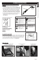
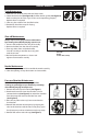
ASSEMBLY INSTRUCTIONS Assemble Extension, Shut-Off, Nozzle and Spray Optimizer 1. Install the extension “wand” onto the shut-off assembly and tighten the nut securely. (See Figure A) 2. (Optional) Install Spray Optimizer for low pressure (low drift) applications. This will help prevent weed killer formulas from drifting into undesired areas. (Do not over tighten, actual position will vary. See Figure B) 3.
OPERATING INSTRUCTIONS Always conduct a test using cool, clean water before mixing chemicals. Filling Always refer to chemical manufacturer for proper mixture. 1. Remove the cap from the tank. 2. Make sure the filter basket is in place in the neck of the tank. The filter basket includes the seal and must be in place to prevent leaks. 3. Fill the tank with cool water and chemical to the desired level. 4. Reinstall the cap. Pressurizing and Spraying 1.
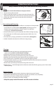
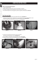
MAINTENANCE Tank Maintenance 1. After each use, rinse the tank with cool, clean water. 2. Check the check valve (See Figure G) and filter basket gasket. (See Figure H) Make sure they do not show signs of wear and are operating properly. Replace them as required. 3. Clean any dirt or debris from the filter basket. 4. Periodically check the straps for fraying. Replace them as required.
SERVICING INSTRUCTIONS Prior to servicing and/or repairs. 1. Empty contents of tank. 2. While squeezing shut-off, pump sprayer until all liquid is expelled. 3. Continue squeezing shut-off without pumping to release all air pressure. 4. You will find all parts for servicing primary seals and gaskets to be included in KIT #32. Tank Servicing Steps 1. Unscrew cap from tank. Remove and replace check valve. (See Figure 1) 2.
SERVICING INSTRUCTIONS CONTINUED 7. Pull upward to slide piston rod out of pump. (See Figure 7) 8. While holding onto the pump, use an adjustable wrench to unthread pump nut from pump. Remove nut, hose and barb assembly. (See Figure 8) 9. Inspect (2) o-rings on barb assembly. If damaged, replace hose assembly. (See Figure 9) Figure 7 Figure 8 Figure 9 10. Remove pump out of tank. Remove and replace gasket. (See Figure 10) 11. Slide piston rod assembly down and out of grommet and remove from tank.
SERVICING INSTRUCTIONS CONTINUED 16. Attach pivot clip to piston rod and insert hitch pin. Note orientation of piston rod must match the pivot clip. (See Figure 16) 17. Reassemble carry handle onto tank. Tighten all (6) screws. (See Figure 5) 18. To reinstall the agitator, line the notch up on the agitator with the swedge on piston rod and snap into place. (See Figure 17) 19. Reinstall pressure chamber as outlined in the Pressure Chamber Maintenance section.
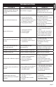
TROUBLESHOOTING TROUBLE LOOK FOR REMEDY Sprayer starts to spray when pumping or sprayer will not stop spraying when shut-off lever is released. Shut-off lock is engaged. Sprayer will not build pressure. 1. Install pressure chamber as described in Pressure 1. Pressure chamber (#2) Chamber Maintenance section. installed into pump (#3). 2. Clean and lubricate or 2. Dirty, damaged or worn pump replace o-rings as described or chamber o-ring (#31A). in Servicing section. 3. Dirty poppet in pump. 3.
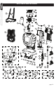
KITS, PARTS & ACCESSORIES KIT #27 27A 13 27B KIT #28 28A 28B 2 26 10 3 31A 9 1-SS 18 31C 31B 1 14 11 8 7 20 31D KIT #29 19 30D 21 29F 12 22 29A 29E 29G 5 30A 4 18 29C 15-SS 15 30B 6 34 30C 29B 29H 29D 29I 29J KIT #30 17 30B 31E 30D 25 24 23 16 31D KIT #31 31A 31C 30F KIT #32 30C 30E 32A 31B 32F 32B 32E 32C 32D 30E KIT #33 33B 33C 33E 33A 33F 33D page 10
KEY# PART# DESCRIPTION 1 1-SS 181700 182104 2 182008 3 4 5 6 7 8 9 10 11 182070 181635 181653 181654 181954 181669 181665 181641 181648 TANK ASSEMBLY TANK ASSEMBLY, STAINLESS STEEL HIGH CAPACITY RESERVOIR / CHAMBER ASSEMBLY PUMP DRIVE SUPPORT SHROUD LEFT BUSHING RIGHT BUSHING DRIVE LEVER ASSEMBLY PUMP PISTON ASSEMBLY STANDARD AGITATOR PIVOT CLIP BACK HANDLE 12 13 14 15 15-SS 16 17 18 19 20 21 22 23 24 25 26 181826 181659 181889 181824 182112 181925 181649 181529 181716 182017 181906 181757 181651 18
SERVICE KITS, PARTS & ACCESSORIES ARE AVAILABLE BY CONTACTING The Fountainhead Group, Inc. - Customer Service Center Monday - Friday 8 a.m. - 5 p.m., EST Toll Free: 1-800-311-9903 or e-mail: Info@TheFGI.com or Access online at: www.TheFountainheadGroup.
Atomizador de Mochila Manual de uso y cuidado PRECAUCIÓN: Lea y siga todas las instrucciones No devuelva este atomizador a la tienda Para obtener ayuda, información o piezas, llame al: 1-800-311-9903 The Fountainhead Group, Inc. 23 Garden St., New York Mills, NY 13417 1-800-311-9903 www.TheFountainheadGroup.com Manual No. 183077 Rev B.
PRECAUCIONES DE SEGURIDAD • Lea todo el manual del usuario antes de operar este atomizador. • Siempre utilice gafas de seguridad, guantes y ropa protectora cuando use el atomizador. • Lea y siga todas las instrucciones y precauciones que se muestran en la etiqueta de los productos que se usan en este atomizador. • Nunca utilice líquidos inflamables, agentes cáusticos, ácidos o agua caliente en este tanque. • No deje el atomizador expuesto al sol cuando no esté en uso.
INSTRUCCIONES DEL ENSAMBLAJE Ensamblado de la extensión, el cierre, la boquilla y el optimizador de rociado 1. Instale la “varilla” de extensión en el dispositivo de cierre y ajuste la tuerca hasta que esté segura. (Vea la Figura A) 2. (Opcional) Instale el Optimizador de Rociado para aplicaciones de baja presión (flujo bajo). Esto ayudará a evitar que las fórmulas para matar la maleza se desplacen hacia áreas indeseadas. (No apriete demasiado, la posición real puede variar. Vea la Figura B) 3.
INSTRUCCIONES DE OPERACIÓN Siempre realice una prueba con agua limpia y fría antes de mezclar sustancias químicas. Llenado (Siempre consulte al fabricante de la sustancia química para saber la mezcla correcta). 1. Quite la tapa del tanque. 2. Asegúrese de que la canasta del filtro se encuentre en su lugar en el cuello del tanque. La canasta de filtro incluye el sello y debe estar instalada para evitar fugas. 3. Llene el tanque con agua fría y la sustancia química hasta el nivel deseado. 4.
MANTENIMIENTO Mantenimiento del tanque 1. Después de cada uso, enjuague el tanque con agua limpia y fría. 2. Revise la válvula de retención (Vea la Figura G) y la junta de la canasta del filtro (Vea la Figura H). Asegúrese de que no presenten señales de desgaste Figura G Figura H y que estén funcionando correctamente. Reemplácelas si es necesario. 3. Limpie cualquier suciedad o residuo de la canasta del filtro. 4. Revise periódicamente las correas para ver si existe algún desgaste.
INSTRUCCIONES PARA DAR MANTENIMIENTO Antes del servicio y/o reparaciones. 1. Vacíe el contenido del tanque. 2. Mientras presiona el dispositivo de cierre, bombee el atomizador hasta que se haya expulsado todo el líquido. 3. Continúe presionando el dispositivo de cierre sin bombear a fin de liberar toda la presión del aire. 4. Descubrirá que todas las partes para mantener los sellos primarios y las juntas están incluidas en el Juego No. 32. Pasos para darle mantenimiento al tanque 1.
INSTRUCCIONES PARA DAR MANTENIMIENTO (continuación) 7. Jale hacia arriba para retirar la varilla de pistón fuera de la bomba. (Vea la Figura 7) 8. Mientras sostiene la bomba, utilice una llave ajustable para retirar la tuerca de la bomba fuera de la bomba. Retire la tuerca, la manguera y la espiga. (Vea la Figura 8) 9. Revise (2) anillos O del ensamblaje de la espiga. Si están dañados, reemplace el ensamblaje de la manguera. (Vea la Figura 9) Figura 7 Figura 8 Figura 9 10.
INSTRUCCIONES PARA DAR MANTENIMIENTO (continuación) 16. Sujete el clip de pivote a la varilla de pistón e inserte la clavija de enganche. Tenga en cuentaque la orientación de la varilla de pistón debe coincidir con el clip de pivote. (Vea la Figura 16) 17. Vuelva a ensamblar el mango de transporte en el tanque. Ajuste los (6) tornillos. (Vea la Figura 5) 18. Para volver a instalar el agitador, alinee la muesca del agitador con el escariador sobre la varilla de pistón y ajuste en su lugar.
SOLUCIÓN DE PROBLEMAS PROBLEMA El atomizador empieza a rociar al bombear o el atomizador no deja de rociar cuando el gatillo de cierre se libera. BUSCAR SOLUCIÓN Presione el mango de cierre y suelte el El seguro del dispositivo de cierre seguro. Vea la sección Presurización y está activado. atomización. 1. Cámara de presión (No. 2) instalada en la bomba (No. 3). 2. La junta tórica de la cámara o No aumenta la presión en el atomizador. la bomba está sucia, dañada o gastada (No. 31A). 3.
JUEGOS, PIEZAS Y ACCESORIOS KIT #27 27A 13 27B KIT #28 28A 28B 2 26 10 3 31A 9 1-SS 18 31C 31B 1 14 11 8 7 20 31D KIT #29 19 30D 21 29F 12 22 29A 29E 29G 5 30A 4 18 29C 15-SS 15 30B 6 34 30C 29B 29H 29D 29I 29J KIT #30 17 30B 31E 30D 25 24 23 16 31D KIT #31 31A 31C 30F KIT #32 30C 30E 32A 31B 32F 32B 32E 32C 32D 30E KIT #33 33B 33C 33E 33A 33F 33D page 22
KIT No.29 181789 JUEGO DE MANGO DE BOMBA ASEGURADO CON TORNILLO (PLEGABLE) No. DE CLAVE No.
LOS JUEGOS DE REPARACIÓN, PIEZAS Y ACCESORIOS SE ENCUENTRAN DISPONIBLES COMUNICÁNDOSE A The Fountainhead Group, Inc. - Centro deservicio al cliente De lunes a viernes de 8 a.m. a 5 p.m., EST Llame sin costo al: 1-800-311-9903 o Correo electrónico: Info@TheFGI.com o Ingrese en línea a: www.TheFountainheadGroup.
Pulvérisatur á sac á dos Manuel d’utilisation et d’entretien ATTENTION : Lisez et suivez toutes les instructions Ne retournez pas ce pulvérisateur au magasin. Pour obtenir de l’aide, de l’information ou des pièces, appelez le 1-800-311-9903 The Fountainhead Group, Inc. 23 Garden St., New York Mills, NY 13417 1-800-311-9903 www.TheFountainheadGroup.com Manual No. 183077 Rev B.
PRÉCAUTIONS DE SÉCURITÉ • Lisez tout le manuel du propriétaire avant d’utiliser ce pulvérisateur. • Portez toujours des lunettes de sécurité, des gants et des vêtements de protection en utilisant le pulvérisateur. • Lisez et suivez toutes les instructions et les mises en garde de l’étiquette des produits utilisés dans ce pulvérisateur. • N’utilisez jamais de liquides inflammables, d’agents corrosifs, d’acides ou d’eau chaude dans ce réservoir.
INSTRUCTIONS D’ASSEMBLAGE Assemblez la rallonge, l’arrêt, la buse et l’optimiseur de pulvérisation 1. Installez la « lance » de rallonge sur l’assemblage d’arrêt et resserrez bien l’écrou. (Voir la igure A) 2. (Optionnel) Installez l’optimiseur de pulvérisation pour des applications à basse pression (faible déplacement). Ceci aidera à empêcher le déplacement des formules d’herbicides vers des endroits indésirables. (Ne resserrez pas trop, la position réelle variera. (Voir la Figure B) 3.
MODE D’EMPLOI Testez toujours avec de l’eau propre et fraîche avant de mélanger les produits chimiques. Remplir Reportez-vous toujours au fabricant de produits chimiques pour le bon mélange. 1. Retirez le bouchon du réservoir. 2. Assurez-vous que le panier-filtre soit en place dans le col du réservoir. Le panier-filtre inclut le joint et doit être en place pour éviter les fuites. 3. Remplissez le réservoir d’eau fraîche et de produits chimiques jusqu’au niveau voulu. 4. Replacez le bouchon.
ENTRETIEN Entretien du réservoir 1. Après chaque utilisation, rincez le réservoir à l’eau propre et fraîche. 2. Vérifiez le clapet (Voir la Figure G) et le joint d’étanchéité du panier-filtre (Voir La Figure H). Assurez-vous qu’il n’y a pas de signes d’usure et que tout fonctionne correctement. Remplacez-les au besoin. 3. Nettoyez toute saleté ou débris du panier-filtre. 4. Vérifiez régulièrement si les sangles s’effilochent. Remplacez-les au besoin.
INSTRUCTIONS D’ENTRETIEN Avant tout entretien et/ou réparations. 1. Videz le contenu du réservoir. 2. En pressant l’arrêt, pompez le pulvérisateur jusqu’à ce que tout le liquide soit sorti. 3. Continuez à presser l’arrêt sans pomper pour dégager toute la pression d’air. 4. Vous trouverez toutes les pièces pour l’entretien des joints et joints d’étanchéité primaires incluses dans la TROUSSE n° 32. Étapes pour l’entretien du réservoir 1. Dévissez le bouchon du réservoir. Retirez et replacez le clapet.
INSTRUCTIONS D’ENTRETIEN SUITE 7. Tirez vers le haut pour glisser la tige du piston hors de la pompe. (Voir la Figure 7) 8. Tenez bien la pompe et utilisez une clé ajustable pour dévisser l’écrou de pompe de la pompe. Retirez l’assemblage d’écrou, de boyau et de barbelure. (Voir la Figure 8) 9. Inspectez (2) joints toriques sur l’assemblage de barbelure. Si endommagé, remplacez l’assemblage du boyau. (Voir la Figure 9) Figure 7 Figure 8 Figure 9 10. Retirez la pompe du réservoir.
INSTRUCTIONS D’ENTRETIEN SUITE 16. Attachez la pince du pivot à la tige du piston et insérez la goupille d’attelage. Notez : que l’orientation de la tige du piston doit correspondre à la pince du pivot. (Voir la Figure 16) 17. Remontez la poignée de transport sur le réservoir. Resserrez les (6) vis. (Voir la Figure 5) 18. Pour réinstaller l’agitateur, alignez l’encoche vers le haut sur l’agitateur avec le coin de la tige du piston et enclenchez en place. (Voir la Figure 17) 19.
PROBLÈME DÉPANNAGE CHERCHER LA Le pulvérisateur commence à pulvériser en pompant ou le pulvérisateur n’arrêtera pas de Le verrou d’arrêt est engagé. pulvériser lorsque la gâchette d’arrêt est dégagée. Le pulvérisateur ne se met pas sous pression. Le pulvérisateur ne pulvérise pas. SOLUTION Pressez la poignée d’arrêt et désengagez le verrou. Voir la section Mettre sous pression et pulvériser. 1. Chambre de pression (N° 2) installée sur la pompe (N° 3). 2.
TROUSSES, PIÈCES ET ACCESSOIRES KIT #27 27A 13 27B KIT #28 28A 28B 2 26 10 3 31A 9 1-SS 18 31C 31B 1 14 11 8 7 20 31D KIT #29 19 30D 21 29F 12 22 29A 29E 29G 5 30A 4 18 29C 15-SS 15 30B 6 34 30C 29B 29H 29D 29I 29J KIT #30 17 30B 31E 30D 25 24 23 16 31D KIT #31 31A 31C 30F KIT #32 30C 30E 32A 31B 32F 32B 32E 32C 32D 30E KIT #33 33B 33C 33E 33A 33F 33D page 34
KIT N° 29 181789 TROUSSE DE POIGNÉE DE POMPE BOULONNÉE (REPLIABLE) N° DE CLÉ N° DE PIÈCE DESCRIPTION 1 181700 ASSEMBLAGE DE RÉSERVOIR 29A 181923 ASSEMBLAGE DE POIGNÉE DE POMPE REPLIABLE (PRISE INCLUS) 182104 ASSEMBLAGE DE RÉSERVOIR, ACIER INOXYDABLE 29B 181753 ARBRE D’ENTRAÎNEMENT BOULONNÉE 2 182008 ASSEMBLAGE DE RÉSERVOIR / CHAMBRE DE FORTE CAPACITÉ 29C 181756 BOULON 29D 181756 CONTRE-ÉCROU 3 182070 POMPE 29E 181772 SANGLE DE RETENUE 4 181635 ENVELOPPE DE SUPPORT D’ENTRAÎNEM
LES TROUSSES DE SERVICE, PIÈCES ET ACCESSOIRES SONT DISPONIBLES EN CONTACTANT The Fountainhead Group, Inc. - Centre de Service à la Clientèle Lundi au vendredi, 8 h à 17 h, HNE Sans frais : 1-800-311-9903 ou courriel : Info@TheFGI.com ou Accès en ligne à : www.TheFountainheadGroup.