h u sqvarna AUTOMOWE R ® 210 C ope r ator’s man ual
TABLE OF CONTENTS 1. Introduction and safety .............................................................. 1.1 Introduction ..................................................................................... 1.2 Symbols on Automower® .......................................................... 1.3 Symbols in the Operator’s Manual .......................................... 1.4 Safety instructions ........................................................................ 5 5 6 7 8 2. Presentation ..........
TABLE OF CONTENTS Husqvarna AB has a policy of continuous product development and therefore reserves the right to modify the design and appearance and function of products without prior notice. This Operator's Manual deals with version 2.7x of the mower’s control program.
1. INTRODUCTION AND SAFETY 1. Introduction and safety 1.1 Introduction Congratulations on your choice of an exceptionally high quality product. To get the best results from your Husqvarna Automower® requires knowledge of its function. This Operator's manual contains important information about the mower, how you install it and how you use it. The following system is used in the Operator's manual to make this easier: • Text written in italics is a reference to another part of the Operator's Manual.
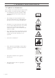
1. INTRODUCTION AND SAFETY 1.2 Symbols on Automower® These symbols can be found on the lawn mover. Study them carefully so you understand their significance. • Read through the Operator’s Manual carefully and understand the content before using your Automower®. • The warnings and safety instructions in this Operator’s Manual must be carefully followed if the mower is to be used safely and efficiently.
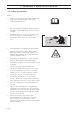
1. INTRODUCTION AND SAFETY 1.3 Symbols in the Operator’s Manual These symbols can be found in the Operator’s Manual. Study them carefully so you understand their significance. • Inspection and/or maintenance must be carried out with the main switch set to OFF. • Always wear protective gloves when working with the mower’s underframe. • Never use a high-pressure washer or even running water to clean Automower®.
1. INTRODUCTION AND SAFETY 1.4 Safety instructions Use • Please read the Operator's Manual carefully and make sure you understand the instructions before using Automower®. • It is not permitted to modify the original design of Automower®. All modifications are made at your own risk. • Check that there are no stones, branches, tools, toys or other objects on the lawn that can damage the blades and cause the mower to stop. • Start Automower® according to the instructions.
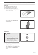
1. INTRODUCTION AND SAFETY Transport The original packaging should be used when transporting Automower® over long distances. To safely move from or within the working area: 1. Move the main switch to the OFF position if you intend to carry the mower. 2. Carry the mower by the handle at the rear of the mower. Carry the mower with the blade disc away from the body. Maintenance WARNING When the mower is turned upside down the main switch must always be set to the OFF position.
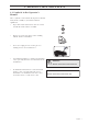
2. PRESENTATION 2. Presentation This chapter contains information you should be aware of when planning the installation. An installation of Husqvarna Automower® comprises three main components: Automower®, an automatic lawn mower that mows the lawn by moving in an irregular pattern. The mower is powered by a maintenance-free battery. Loop generator/charger. The loop generator/charger has two functions: • To send control signals along the boundary wire. • To charge the battery in Automower®.
2. PRESENTATION 2.1 Automower®, what’s what? 1 6 2 6 5 9 7 3 4 8 14 13 16 10 11 17 12 18 15 19 20 21 22 23 The numbers in the picture correspond to: 1. 2. 3. 4. 5. 6. 7. 8. 9. 10. 11. 12. 13. Cutting height adjustment cover Catch button to open the cutting height adjustment cover Front wheel Drive wheel Body Stop button Indicator lamps Keypad Main switch Handle Charger contact Chassis box with electronics, battery and motors Skid plate 14. 15. 16. 17. 18. 19. 20. 21.
2. PRESENTATION 2.2 Function of Automower® Capacity Automower® is recommended for lawns up to 500 m2. The size of the working area the mower can handle depends on how much it is used. The larger the lawn the more occasions per week the Automower® can work. How large an area is mown per hour depends primarily on the condition of the blades and the type of grass, growth rate and humidity. The shape of the garden is also significant.
2. PRESENTATION When there is a risk of thunder Automower® should not stand in the charging station. When there is a risk of a thunder storm, the 230 V plug should be removed from the mains socket and the boundary wire disconnected from the charging station. The blades must be in good condition to obtain the best mowing result. In order to keep the blades sharp for as long as possible it is important to keep the lawn free from branches, small stones and other objects.
2. PRESENTATION A four digit PIN code must be chosen and entered when the main switch is set in the ON position for the first time. (see page 30). The chosen PIN code must then be entered each time the mower is started. If the mower does not start within 20 seconds the PIN code must be re-entered until the mower starts. Slide shut the cover to start the mower after the PIN code has been entered. Automower® can, to save energy, enter sleep mode.
3. INSTALLATION 3. Installation This chapter describes how you install Husqvarna Automower®. Before starting the installation read the previous chapter 2. Presentation. Read the whole of this chapter too before starting the installation. How the installation is made also affects how well Automower® will work. It is therefore important to plan the installation carefully. Planning is simplified if you make a sketch of the working area, including all obstacles.
3. INSTALLATION 3.2 Installation of the loop generator/charger The loop generator/charger must be placed where it is well ventilated and is not exposed to direct sunlight. The mower's battery is spared if it is charged in the lowest possible ambient temperature. It is also beneficial if the transformer can be placed under a roof. IMPORTANT INFORMATION The power cord for the loop generator/charger must not be replaced.
3. INSTALLATION 3.3 Charging the battery Automower® is supplied with an uncharged battery. As soon as the loop generator/charger is connected, it is possible to charge the mower. 1. Set the main switch to the ON position and leave the cover for the control panel open. 2. Connect the charger cable from the loop generator/charger to the charger contact on the mower. The green indictator lamp Battery now goes on.
3. INSTALLATION Best position for the boundary wire The boundary wire should be laid so it: • Forms a loop around the working area for Automower®. Only an original boundary wire must be used. This is tinned and has a high quality insulation to withstand the dampness in the ground. • Is a maximum of 350 metres long. • Maintains a maximum distance of 25 metres from Automower® in the entire working area.
3. INSTALLATION Boundaries for the working area If a high obstacle, for example a wall or fence, borders the working area, the boundary wire should be laid 35 cm from the obstacle. This will prevent Automower® from colliding with the obstacle and reduce body wear. 35 cm If the working area borders against a small ditch, for example, a flower bed or a small elevation, e.g. a low verge (3 - 5 cm), the boundary wire should be laid 30 cm inside the working area.
3. INSTALLATION Boundaries within the working area Use the boundary wire to demarcate areas inside the working area by creating islands around obstacles that can not withstand a collision, for example, flower beds and fountains. Run the cable out to the area, route it around the area to be demarcated and then back along the same route. If staples are used, the wire should be laid under the same staple on the return route.
3. INSTALLATION Secondary areas It is recommended to create a secondary area when the working area is made up of two areas that are joined by a passage where the distance between the boundary wires is less than 60 cm. Run the boundary wire then around the secondary area so that it forms an island outside of the main area. Secondary area Automower® must be moved manually between the main and secondary areas.
3. INSTALLATION Automower® can mow areas inside the working area that slope up to 35 cm per distance metre (35 %). Areas that slope more must be demarcated by the boundary wire. When any part of the working area's boundary slopes more than 10 cm per distance metre (10 %), the boundary wire must be routed about 35 cm in on flat ground before the slope starts. Laying out the boundary wire Run the boundary wire around the working area, but wait before connecting the wire to the loop generator/charger.
3. INSTALLATION • Make sure to lay the boundary wire tight to the ground and secure the staples close together with approximately 75 cm between each staple. The wire must generally lie close to the ground so, as not to be cut off before the grass roots have grown over it. • Use a hammer to knock down the staples in the ground. Exercise care when knocking in the staples and make sure the wire is not under strain. Avoid forming the wire in sharp bends.
3. INSTALLATION Joining the boundary wire If the boundary wire is not long enough and needs to be spliced: Use original solderless coupler. It is waterproof and gives a reliable electrical connection. To splice: Insert both cable ends in the coupler. Now press down the button on top of the connector fully. Use a pair of pliers or the like, as the button on the connector is difficult to press down by hand.
3. INSTALLATION 3. Cut off any surplus boundary wire. Cut 1 - 2 cm above respective connectors. 4. Attach the connector to the contact pin on the loop generator/charger. 3.6 Checking the installation Check the loop signal by looking to see what indication the green LED on the loop generator/charger is giving. • Steady light = the signal is okay. • Flashing once every other second = break in the loop and no signal found. • Flashing twice every other second = weak signal.
3. INSTALLATION 3.7 Linking Automower® to the loop generator/charger 1. Connect the loop generator/charger charging cable to the mower's charger contact. At most the mower may be two metres from the working area's boundary wire and the loop generator/charger must be connected to the mains supply. 2. Open the control panel cover by pressing the STOP button. Set the main switch to the ON position. 2m 3. The yellow indicator lamp PIN code should now flash. 4. Select and enter a four digit PIN code.
4. USE 4. Use 4.1 Starting Automower® WARNING Read the safety instructions before you start your Automower®. WARNING Keep your hands and feet away from the rotating blades. Never put your hands or feet close to or under the body when the motor is running. 1. Press the STOP button to open the control panel cover on Husqvarna Automower®. 2. Set the main switch to the ON position. 3. Enter the PIN code, confirm with the YES button. 4. Close the cover.
4. USE 4.3 Restart To start: 1. Enter the PIN code. 2. Press the YES button. 3. Close the control panel cover. 4.4 Switching off Automower® 1. Press the STOP button. 2. Set the main switch to the OFF position. Always switch off Automower® using the main switch if you intend to perform maintenance or move the mower outside of the working area. 4.5 Using the Timer The lawn should not be mown for too long to obtain the best result.
4. USE 4.6 Adjusting the cutting height The cutting height can be varied from MIN (2 cm) to MAX (6 cm). If the grass is long it is appropriate to let Automower® start mowing at the MAX cutting height. Once the grass is shorter, you can gradually lower the cutting height. To adjust the cutting height: 1. Press the STOP button to stop the mower. 2. Open the cutting height adjustment cover: Press down the catch button and then open the cover. 3. Turn the knob to the required position.
4. USE 4.7 Changing the PIN code To change the PIN code on the mower: 1. Connect the loop generator/charger charging cable to the mower's charger contact. At most the mower may be two metres from the working area's boundary wire and the loop generator/charger must be connected to the mains supply. 2. Open the control panel cover by pressing the STOP button. Set the main switch to the ON position. 3. State the current PIN code, confirm by pressing the YES button. 4.
4. USE 4.9 Sounds The mower indicates the operating status and all input with audio signals as set out below.
5. CONTROL PANEL 5. Control panel The control panel on Husqvarna Automower® consists of indicator lamps and a keypad. All information is shown through the indicator lamps and all input is done using the buttons. The control panel consists of three groups of buttons: select, numbers and main switch, and indicator lamps.. 5.1 Select 1. Cancel: • Press to interrupt an ongoing input or to reset the mower when a fault message is shown. 2. YES: • Press to confirm the entered PIN code. 1 5.2 Numbers 3.
5. CONTROL PANEL 5.3 Main switch 4. Set the main switch in the ON position to start Automower®. Set the main switch in the OFF position when you are not using the mower or if you want to work on the blade disc. 4 When the main switch is set in the OFF position the motors on the mower cannot start. 5.4 Indicator lamps The indicator lamps indicate the status of the mower. If all the lamps are out, the mower is in sleep mode. Start the mower again by switching the main switch off and on. 5.
6. GARDEN EXAMPLE 6. Garden example - Proposed installation An number of installations of Husqvarna Automower® in different types of gardens are shown and explained in this chapter. See the examples as pointers for how to make the installation in your garden as good as possible. Also see 3. Installation on page 15. Proposals for installation Open garden with narrow passages and obstacles, area: 300 m2. The boundary wire has be routed around delicate bushes and the outer edges of the garden.
6. GARDEN EXAMPLE Proposals for installation Garden with a steep incline (30 %) that divides the garden into two areas, area: 400 m2. If the mowing result between the areas is uneven, the garden can ideally be divided into two zones The mower may find it difficult to climb steep inclines, consequently a garden with steep inclines can be mown unevenly, even if there are no passages. zone 2 zone 1 Two gardens with the area 200 m2.
7. MAINTENANCE 7. Maintenance Check and clean Husqvarna Automower® regularly and replace worn parts if necessary to improve operating reliability and to ensure a longer service life. For further information on cleaning, see 7.4 Cleaning on page 39. During the initial period Automower® is used the blade disc, skid plate and blades should be checked once a week. If the amount of wear during this period has been low, the inspection interval can be increased. It is important that the blade disc rotates easily.
7. MAINTENANCE 7.2 Winter storage Automower® Automower® must be carefully cleaned before winter storage, see 7.4 Cleaning on page 39. Automower® should not be continuously charged during the winter. Charge the battery fully before winter storage. Turn the main switch to the OFF position. It is also recommended to fully charge the battery sometime during the winter. This will prolong the battery life. The mower should then be charged for about 24 hours.
7. MAINTENANCE 7.4 Cleaning It is important to keep Automower® clean. A mower with a large amount of clippings negotiates slopes very poorly. It is recommended to clean using a brush and a spray with water. IMPORTANT INFORMATION Never use a high-pressure washer or even running water to clean the Automower®. Solvent must never be used when cleaning. Underframe and blade disc 1. Set the main switch to the OFF position. 2. Wear protective gloves. 3. Lift Automower® onto its side. 4.
7. MAINTENANCE Body Use a damp, soft sponge or cloth to clean the body. If the body is very dirty it may be necessary to use a soap solution or washing-up liquid. 7.5 Replacing the blades WARNING Always use originalblades and screws when replacing. Only replacing the blades and reusing the screw can result in the screw wearing during mowing and shearing off. The blades can then be thrown out and cause serious injury. There are three blades on Automower®, which are screwed into the blade disc.
7. MAINTENANCE Blade type Quantity/Packaging Part number Carbon steel (two-toothed) 9 535 13 87-02 30 535 13 88-02 500 535 12 78-02 9 522 85 16-02 30 522 85 17-02 300 522 85 18-02 Carbon steel (two-toothed, turnable, extra robust) To replace the blades: 1. Set the main switch to the OFF position. 2. Wear protective gloves. 3. Turn Automower® upside down. 4. Rotate the skid plate so that its hole aligns with the screw for the blade. 5. Unscrew the blade.
8. TROUBLE SHOOTING 8. Trouble shooting 8.1 Fault messages A number of fault messages that can be shown by the red Fault indicator lamp on Husqvarna Automower® are shown below. The fault message is interpreted by reading how the lamp flashes. The lamp flashes one to five times in quick succession and then goes out for 2 seconds. This sequence is repeated until the Cancel button is pressed.
8. TROUBLE SHOOTING Flashes Fault message Cause Action 2 No loop signal If this occurs in isolated areas it may be due to interference from metallic objects (perimeter fence, reinforcement bar) or buried cables in the vicinity. Try moving the boundary wire. 3 No drive Automower® has got caught in something. Free the mower and rectify the reason for the lack of drive. If it is due to wet grass, wait until the lawn has dried before using the mower.
8. TROUBLE SHOOTING 8.2 Fault symptom If your Automower® does not work correctly, follow the trouble shooting guide below. If the fault persists; contact your dealer. Symptom Cause Action Uneven mowing results Automower® works too few hours per week. Increase the mowing time. Working area too large. Try limiting the working area or extending the mowing time. Dull blades. Replace all the blades and screws so that the rotating parts are balanced. Long grass in relation to the set cutting height.
9. TECHNICAL DATA 9. Technical data Data Automower® 210 C Dimensions Length 76 cm Width 55 cm Height 30 cm Weight 9.
10. ENVIRONMENTAL INFORMATION 10. Environmental information The symbol on Husqvarna Automower® or its packaging indicates that this product may not be treated as household waste. Instead it shall be handed over to the applicable collection point for the recycling of electrical and It should instead be left at a suitable recycling centre to recycle its electronic components and batteries. Contact your dealer for a disassembly of the batteries.
11.
ORIGINAL INSTRUCTIONS AUTOMOWER is a trademark owned by Husqvarna AB. Copyright © 2010 HUSQVARNA. All rights reserved.