225B 225BX-SERIES Operator´s manual Read the operator’s manual carefully and make sure that you understand the contents before using the blower.
CONTENTS Introduction ......................................... 3 Key to symbols .................................... 4 Safety instructions .............................. 5 Description .......................................... 7 Fuel handling ..................................... 12 Start and stop .................................... 14 Using the blower ............................... 16 Maintenance ...................................... 20 Technical data....................................
INTRODUCTION Husqvarna AB has a policy of continuous product development and therefore reserves the right to modify the design and appearance of products without prior notice. This operator’s manual describes in detail how to use and service the blower and how to carry out regular maintenance. It also describes which measures should be taken to achieve maximum safety while operating the blower, how the safety devices work and how they should be serviced.
KEY TO SYMBOLS The blower operator must make sure that no bystanders or animals come nearer than 10 metres. Whenever several operators are working in the same work area, they should maintain a safe distance of at least 10 metres from one another. X X Cleaning at regular intervals is required. Approved protect goggles or visor must be worn. Approved protect goggles or visor and ear protection must be worn. WARNING! The blower can be dangerous! Careless or improper use can cause serious, even fatal injury.
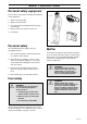
SAFETY INSTRUCTIONS Personal safety equipment Persons who use the blower shall wear the following safety equipment: 1+2 3 1. Approved ear protection. 2. Approved eye protection. 3. Face mask when operating the blower in dusty environments. 4. Boots or work shoes with a non-slip sole. 5. First-aid kit. 4 5 Personal safety The following instructions apply to persons operating the blower: Muffler 1. The operator shall have read and understood the contents of this manual.
SAFETY INSTRUCTIONS Safety equipment ! WARNING! The blower must never be used if any of the safety devices or guards are missing, damaged or not in working order. The blower is equipped with a number of safety devices and guards for the prevention of accidents. These are described in the general description of the blower on page 8. The safety devices and guards also require regular inspection and maintenance.
DESCRIPTION The blower 1 2 3 4 5 6 10 18 9 7 19 17 8 16 21 7 15 14 20 7 13 12 11 225BX-SERIES 1. 2. 3. 4. 5. 6. 7. 8. 9. 10. 11. Shoulder strap Throttle trigger Stop switch Throttle lock Shoulder strap ring Anti-vibration system (inside the housing) Fan housing Fuel cap Air filter Choke Inspection cover (225BX-SERIES) 12. 13. 14. 15. 16. 17. 18. 19. 20. 21.
DESCRIPTION Accessories (225BX-SERIES) 21 25 22 23 24 21. Vacuum device with collection components consisting of items 22 - 25 below. 22. Vacuum bag tube. 23. Collection bag. 24. Vacuum tube in two sections. 25. Auxiliary handle.
DESCRIPTION Safety equipment The following equipment on the blower is designed for protecting personnel and materials. These components should receive special attention whenever you operate, inspect and service the blower. 3 4 Stop switch (3) The stop switch is used to stop the engine. Throttle lock (4) 2 The throttle lock prevents inadvertent activation of the throttle. When the throttle lock is pressed into the handle (when gripping the handle) the throttle trigger (2) is disengaged.
DESCRIPTION Other equipment Throttle trigger (2) The speed and the output of the engine are regulated by the throttle trigger. The throttle lock (4) must be pressed down before the trigger will actuate the throttle. 2 4 Fan casing (7) The blower fan casing (7) together with the impeller (13) provide high performance air discharge. Inspection cover(225BX-SERIES) (11) An inspection cover is located on the underside of the fan casing.
DESCRIPTION Starter device (18) and starter handle (17) The starter device is located at the top on the engine shrouding and engages in the crank shaft only when the starter handle is pulled. 17 18 Fuel cap (8) The fuel cap (14) is located at the top of the engine shrouding and has a gasket, which prevents fuel from leaking out. 8 9 Air filter (9) The air filter consists of foam-rubber filter medium, integrated in a plastic casing. The air filter should be cleaned at specific intervals.
FUEL HANDLING Fuel mixture NOTE! The machine is fitted with a two-stroke engine and must always be run on a mixture of gasoline and two-stroke oil. It is important to measure the quantity of oil accurately, to ensure the correct mixture ratio. Small discrepancies in the amount of oil have a great bearing on the proportions of the fuel mixture when mixing small amounts of fuel. ! WARNING! Allow adequate ventilation while handling fuel.
FUEL HANDLING Mixture • Always mix gasoline and oil in a clean container intended for fuel. • Always start by filling half the quantity of gasoline required. Then add the entire oil quantity. Mix (shake) the fuel mixture. Fill the remaining quantity of gasoline. • Mix (shake) the fuel mixture carefully before filling in the machine‘s fuel tank. • Do not mix more than max. one month’s supply of fuel. • If the machine is not used for a long period of time, the fuel tank should be emptied and cleaned.
START AND STOP Start and stop Start ! WARNING! Never start the blower if the inspection cover is not closed, is damaged or cannot be closed. (Exception: When the vacuum tube is fitted). Cold engine A IGNITION: Set the stop switch to the start position. CHOKE: Set the choke control in the choke position (A). The choke position is also the automatic start throttle position. AIR PURGE: Press the air purge diaphragm repeatedly until fuel begins to fill the diaphragm.
START AND STOP Press the machine body against the ground using your left hand (NOTE! Do not use your foot). Grip the starter handle with your right hand and slowly pull the starter cord out until you feel some resistance, (the starter hooks grip) now quickly and powerfully pull the cord. Immediately press the choke control in when the engine fires and repeat until the engine starts. When the engine starts, quickly apply full throttle and the start throttle will automatically disengage.
USING THE BLOWER To blow away debris on the ground Fitting the blower tube and nozzle on the blower ! WARNING! When fitting the blower tube and nozzle, the engine must be switched off and the stop switch must be in the stop position. 15 The blower tube and nozzle have a bayonet mount. Fit them in the following manner: 1. Press the blower tube (15) against the blower air outlet and turn it 90 degrees until a snap is heard. 2.
USING THE BLOWER ! WARNING! Never point the blower nozzle at people or animals. The high-velocity air stream can contain particles that may cause serious injury, especially if the blower has previously been used for vacuuming. Be careful, particurlarly if left hand operation is applied. Avoid any direct body contact with the exhaust outlet area. ! WARNING! Never start the blower if the inspection cover is not closed, is damaged or cannot be closed. (Exception: When the vacuum tube is fitted).
USING THE BLOWER To vacuum debris from the ground (225BX-SERIES) The vacuuming device is an accessory and is not included in the standard supply. 25 Fitting the collection bag with the various vacuum tubes ! WARNING! When fitting the tubes to the blower, the engine must be switched off and the stop switch must be in the stop position. 22 23 1. Open the collection bag. Insert the collection bag tube from inside the bag to fit in the vacuum inlet opening of the bag as illustrated in the adjacent figure.
USING THE BLOWER When operating the blower, the blower and collection bag must be secured in the shoulder strap. The strap should be worn over the shoulder as shown in the adjacent figure. ! WARNING! Always check that the collection bag is intact and the zipper is closed before starting the blower. Never use a damaged bag. There is risk of injury due to flying debris. Be careful, particurlarly if left hand operation is applied. Avoid any direct body contact with the exhaust outlet area.
MAINTENANCE Carburetor Basic (factory) settings The carburetor has been carefully preset at the factory. However, additional adjustment may be required due to climate, altitude, gasoline and type of twostroke engine oil used. The instructions below describe how carburetor adjustment should be carried out. The carburetor is preset to the basic settings when the blower is tested at the factory. These basic settings are the following: The carburetor governs the engine speed via the throttle.
MAINTENANCE Muffler NOTE! Some mufflers are fitted with a catalytic converter. See “Technical data” to see whether you clearing saw is fitted with a catalytic converter. The muffler is designed to dampen the noise level and to direct the exhaust fumes away from the user. The exhaust fumes are hot and can contain sparks, which can result in fire if the exhaust fumes are directed towards a dry and inflammable material. Some mufflers are equipped with a special spark arrest screen.
MAINTENANCE Air filter The air filter (A) must be cleaned regularly to remove dust and dirt. This will prevent: • • • • • • Carburetor malfunctions Starting problems Reduced performance Unnecessary wear on engine parts Abnormal fuel consumption Elevated content of harmful exhaust fumes B A Clean the filter after 25 hours of operation or more often if the air is exceptionally dusty in the work area. To clean the air filter Dismantle the air filter cover (B) and remove the filter medium.
MAINTENANCE Maintenance schedule A number of general maintenance instructions are given below. If more detailed instructions are required, get in touch with your local servicing dealer. Daily maintenance 1 2+3 1. Clean the exterior surfaces of the blower. 2. Check that the throttle lock and the throttle trigger function in a safe manner. Replace damaged parts. 3. Check that the stop switch works properly. Replace if necessary. 4 4. Clean the filter. Replace it, if required. 5.
MAINTENANCE Monthly maintenance 1. Flush the fuel tank with clean gasoline, which afterward should be disposed of in an environmentally correct manner. 2. Clean the outside of the carburetor and the space around it. Replace damaged parts. 3. Clean the fan blades on the flywheel and the space around it. 2 4. Check the fuel filter and the fuel line. Replace them, if necessary. 5. Check all the cables and the connections. Replace damaged parts. 6. Change the spark plug. 3 7.
TECHNICAL DATA 225B 225BX-SERIES Engine Cylinder volume, cm3: Cylinder bore, mm: Stroke, mm: Idling speed, rpm: Max. speed – blowing, rpm: Max. speed – vacuuming, rpm: Max. engine output to ISO 8893: Catalytic converter muffler 26,9 35 28 3.000 8.200 7.400 0.9 kW/9000 rpm No 26,9 35 28 3.000 8.200 7.400 0.9 kW/9000 rpm Yes Ignition system Manufacturer/type of ignition system: Spark plug: Electrode gap, mm: Walbro CD Champion RCJ 7Y 0.5 Walbro CD Champion RCJ 7Y 0.
FEDERAL AND CALIFORNIA EMISSION CONTROL WARRANTY STATEMENT YOUR WARRANTY RIGHTS AND OBLIGATIONS The EPA (U.S. Environmental Protection Agency), CARB (California Air Resources Board) and Husqvarna Forest & Garden are pleased to explain the emissions control system warranty on your 2001 and later small off-road engine. In U.S., new small off-road engines must be designed, built and equipped to meet the federal and California stringent anti-smog standards.
English – 27
´+H"[¶5B¨ 2001W32