Workshop Manual 23/26/32 LC/L 531 03 00-75
H Warranty the FOREST& U GARDEN Effective May 1, 1992 SECTION1: LIMITEDWARRANTY Husqvarna Forest & Garden Company (“Husqvarna”) warrants Husqvarna product to the original purchaserto be free from defective materialand workmanshipfrom the date of purchasefor Period” here stated dependent upon the type of productiveWarranty period as follows for products listed: 5 YEAR WARRANTY: Plastic walk behind mower decks for noncommercial,noninstitutionalor nonincome producing use.
2 HUSQVARNA WARRANTY 3 MODEL SPECIFICATIONS 4 TROUBLE SHOOTING Suggestions Cause/Remedy Chart 6 SHIELD Attachment 7 TRIMMER HEAD Head Installation Spool Installation Proper Line Feed Reassembly 11 DRIVE SHAFT Lubrication 13 THROTTLE CABLE Removal & Installation 16 ELECTRICAL SYSTEMS Spark Plug Replacement Checking for Spark Ignition Switch 19 CARBURETOR & FUEL SYSTEMS Air Filter Removal & Cleaning Carburetor Acceleration & Deceleration Checks Speed & Mixture Adjustments 25 CLUTCH SYSTEM C
TROUBLE SHOOTING SUGGESTIONS ● ● ● ● ● ● Engine will not continue to run at idle position. See “Idle Speed Adjustment” and “Low Speed Mixture Adjustment” Trimmer head continues to spin when the engine idles. See “Idle Speed Adjustment>> and “Deceleration Check>’. Engine dies or hesitates when it should accelerate. see “Acceleration Check”. Loss of cutting power which cannot be corrected by cleaning the air filter. See “High Speed Mixture Adjustment”.
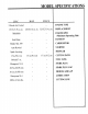
SPECIFICATION MODEL 23LC 26LC 32LC/L 2-Stroke AirCooled - — 23CC/1.35cu.in. 26CC/1.6cu.in. 32CC/1.9cu.in. ENGINETYPE DISPLACEMENT 7500/3000 — ENGINERPM (MaximumOperating/Idle) SolidState — IGNITION WalbroWA-199 — CARBURETOR AutoRewind — STARTER SparkArresting — MUFFLER CUTTINGPATH 15in./3802 cm 15in./38.2cm 17in./43.2cm 500ml/17oz. — — FUELTANK Champion CJ-14 — — SPARKPLUG .025in./O.635 mm — — SPARKPLUGGAP .012in./O.
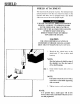
SHIELD SHIELD ATTACHMENT The shield must be properly installed. The shield provides partial protection from the risk of thrown objects to the operator and others and is equipped with a line limiter which cuts excess line to the proper length. FAILURE TO INSTALL SHIELD IN POSITION SHOWN CAN RESULT IN SERIOUS INJURY TO THE OPERATOR. THE LENGTH OF SHIELD MUST BE ALIGNED WITH LENGTH OF DRIVE SHAFT HOUSING. DIRECT WIDEST PART OF SHIELD TOWARDS THE ENGINE.
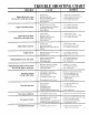
1. 2. 10cm TINGCHART TROUBLE SHOO TROUBLE REMEDY CAUSE Enginewillnotstartor runs for onlya fewsecondsafterstarting. 1. 2 3 4 5. Fueltankempty, Sparkplugisnotfiring. Fuelisnotreachingthecarburetor. Carburetor needsadjustment. Noneoftheabove. 1. 2. 3. 4. Enginewillnotidleproperly. 1. 2. 3. 4. Idlespeedsettoofastortooslow. Lowspeedmixturerequiresadjustment. Throttletriggersettootight. Noneoftheabove. 1. See“Carburetor Adjustments”. 2. See“Carburetor Adjustments”. 3. See“Carburetor Adjustments”.
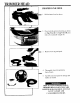
TRIMMER HEAD PROPER LINE FEED 1. Hold trimmer head as shown. 2. Press lock tab and turn lock ring as shown on Tap-N-Go II. For Tap-N-Go 111press lock tabs in and pull straight off. 3. Remove lock ring and spool. 4. Thoroughly clean dirt and debris from all parts. 5. Carefully check all parts for damage and replace as needed. REPLACE ALL DAMAGED PARTS. TRIMMER HEAD PARTS THAT ARE CHIPPED OR DAMAGED IN ANY WAY CAN FLY APART AND CAUSE SERIOUS INJURY.
TRIMMER HEAD INSTALLATION & REMOVAL I r 1. Place dust cap over hex nut located on end of drive shaft housing. I 2. Once in place hold dust cap with a wrench to prevent arbor shift from turning on 26 RLC and 26 LC units. On straight shaft units use the locking pin to hold dust cap from turning. 3. Thread trimmer head onto arbor shaft by rotating head (clockwise for curve shaft units, counterclockwise for straight shaft units) against dust cap and tighten by hand. 4.
TRIMMER HEAD 9. Carefully check to make sure all three catches and lock tab are fastened properly as shown (test lock ring by trying to turn it counterclockwise) on Tap-N-Go II / H 10. Depress top button and pull on the line to change spool from locked position to operating position. 11. To get correct line length (lOcm or 4 inches as measured from spool to the tip of each line) press button and pull on line again.
TRIMMER HEAD TRIMMER HEAD REASSEMBLY ,:., ... 6. Insert end of line into line exit hole. e ::,,/. . ,. 7. Place spool in hub. (Make sure trimmer line is not caught between rim of the spool and the hub.) 8. Align lock ring over the three catches on the hub. Push lock ring down onto hub and turn clockwise as shown. I ..
4. Remove drive shaft from drive shaft housing. 5. Check drive shaft for broken wires, twists, or kinks, replace as necessary. 6. Use a clean cloth to thoroughly wipe old grease or dirt from drive shaft. I I 7. Apply a uniform coat of drive shaft lubricant to entire surface of drive shaft. — 8. Replace drive shaft in drive shaft housing. Turn shaft until it seats in bottom housing. To check this turn drive shaft by hand. Trimmer head should rotate. 9. Reassemble drive shaft housing into engine.
DRIVE SHAFT 2. Carefully pull throttle trigger away from foam grip handle, then remove barrel end of throttle cable from the throttle trigger. Carefully pull throttle cable out of foam grip. 1 3. Loosen clutch shroud screws and remove drive shaft housing from engine.
THROTTLE CABLE 2. Secure throttle cable under plastic retaining clip. NOTE: Do not excessively bend or kink the throttle cable! 3. Align posts on end of cable attachment head with the correct post holes shown. = 4. Install screw through cable attachment head with a 4mm hex wrench. 5. Place throttle cable end into hole on adjustment side of carburetor and reinstall fuel line. .
THROTTLE CABLE THROTTLE CABLE REMOVAL 1. Remove screw and nut from throttle trigger housing. 2. throttle trigger. I 3. Carefully pull throttle cable 01 4. Remove air filter cover. ( SEE AIR FILTER SECTI~ 5. Remove the two screws securing choke plate and carburetor assembly. Remove fuel line and plug to avoid gas leakage. Remove throttle cable from carburetor. 6. Remove the 4mm screw securing cable attachment head and remove cable from around clip. 7.
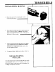
~LECTRICAL SYSTEMS SPARK PLUG REPLACEMENT ~ 1. On 26 LC and 32 LC units the spark plug is located under the engine cylinder cover. Remove the 4 four (mm) screws to gain access to the spark plug. 2. Remove ignition lead from spark plug. 3. Unscrew spark plug, counterclockwise, using a 3/4” socket. ~ - 4. The spark plug electrode gap is 0.025 in. (.635mm). 5. When installing a new plug, tighten it 1/4 turn past finger tight. 6. Replace spark plug lead and top cover for LC units.
THROTTLE CABLE 6. Align carburetor holes with shroud assembly holes and be sure carburetor gasket remains in place. NOTE: Be sure impulse hole on carburetor aligns with pulse hole on shroud and mounting gasket does not interfere with pulse passage. 7. Reinstall screws choke into carbu shroud assembly 8. Reinstall air filter. 9. Reinstall throttle c 1 thru 3 (page 13).
ELECTRICAL SYSTEMS IGNITION SWITCH The ignition switch is located in different areas depending on trimmer model. For 26 RLC and 32 RLC models the switch is located on the engine cover. For 26 LC and 32 LC models the switch is located either on the engine cylinder cover or next to the throttle trigger mounted on the trimmer shaft. STEPS 1 THRU 4 ARE FOR LC MODELS ONLY .- I 1. Remove screwI and nut from throttle trigger housing. 2. Remove the PIIillip screw from switch cover. 3.
ELECTRICAL SYSTEM! CHECKING FOR SPARK 1. Remove the spark plug using spark plug replacement procedure 1thru 3 and clean off all carbon, dirt and other deposits. Check the gap between the electrodes. The air gap should be 0.25in (.635mm). 2. Ground sparkplug to cylinder and turn stop switch on, give the starter rope one hard pull. A spark should occur between the electrodes. — 3. If no spark occurs, test with a new spark plug or test plug. 4. Ifstil no spark occurs, disconnect leads for on/off switc i.
:ARBURETOR &F1 — —.—————— —— ACCELERATION CHECK 1. Allow engine to idle. 2. Squeeze trigger fully. a. If performance is satisfactory, refer to “Deceleration Check”. b. IF ENGINE ACCELERATION IS SLOW OR ERRATIC, repeat “Idle Speed Adjustment” (page 23) or continue through low speed mixture adjustments to obtain proper acceleration. 3. Repeat step 2 until smooth acceleration is obtained. NOTE: It maybe necessary to repeat “Idle Speed Adjustment Acceleration Checks” to obtain correct adjustments.
CARBURETOR &FUELSYSTEMS 1. I 2. Remove air filter from cover. ~ 3. Wash air filter with soap and hot water. DO NOT CLEAN AIR FILTER WITH GASOLINE OR ANY OTHER FLAMMABLE SOLVENT TO AVOID CREATING A FIRE HAZARD! I 4. Squeeze the filter and allow to air dry. CAUTION MAKE SURE AIR FILTER IS SECURELY FITTED INTO CORNERS OF COVER TO KEEP DUST FROM ENTERING THE ENGINE AND CAUSING DAMAGE. 1= 5. Reinstall air filter cover. Make sure choke exit slot is placed over choke lever.
CARBURETOR &FUELSYSTEMS IMPORTANT : ALL CARBURETOR ADJUSTMENTS SHOULD BE MADE WITH A ENGINE TACHOMETER TO ACHIEVE ACCURATE SETTINGS. IDLE NOTE: In most cases, your engine can be made to run properly with minor carburetor adjustment. Refer to “TROUBLE SHOOTING SUGGESTIONS” for the condition you are experiencing and follow the correct instructions. The basic carburetor settings are provided below. 1. Rotate the low and high speed mixture screw clockwise to a lightly seated position.
—— ——— —.———.—— — —. CARBURETOli &FUELSYSTEM! MAKE CARBURETOR ADJUSTMENTS WITH THE DRIVE SHAFT HOUSING SUPPORTED TO PREVENT TRIMMER LINE FROM COMING INTO CONTACT WITH ANY OBJECTS. HOLD TRIMMER WITH YOUR HAND; DO NOT USE OPTIONAL SHOULDER STRAP FOR SUPPORT. KEEP BYSTANDERS AWAY WHEN MAKING CARBURETOR ADJUSTMENTS. I IDliE-/ CARBURETOR ADJUSTMENTS ● ● ● Poor engine performance can be a result of other causes such as a dirty air filter or carbon buildup on muffler outlets, etc.
CARBURETOR &F JELSYSTEMS 5. The trimmer head should not rotate after thelowspeed has been adjusted. If so repeat the IDLE SPEED ADJUSTMENT procedure and check LOW SPEED MIXTURE ADJUSTMENT again. CAUTION THE TRIMMER HEAD MUST NOT ROTATEAT IDLE. RECHECK IDLE SPEED AFTER EVERY CARBURETOR ADJUSTMENT. CAUTION DO NOT OPERATE THE ENGINE AT FULL THROTTLE FOR PROLONGED PERIODS WHILE MAKING HIGH SPEED ADJUSTMENTS AS DAMAGE TO ENGINE CAN OCCUR ! IDLE E 1 HIGH SPEED MIXTURE ADJUSTMENT 1.
t &FUELSYSTEMS CARBURETO IDLE SPEED ADJUSTMENT 1. Allow engine toidle. 2. Adjust idle speed screw just below clutch engagement speed. The cutting attachment should not rotate. The proper idle speed is 2600 to 3400 R.P.M. UxE [ NOTE: Turning the screw clockwise will increase engine R.P.M. counterclockwise will decrease R.P.M. CAUTION THE TRIMMER HEAD MUST NOT ROTATEAT IDLE. RECHECK IDLE SPEED AFTER EVERY CARBURETOR ADJUSTMENT. LOW SPEED MIXTURE ADJUSTMENT 1 d ,,’ ~ ~ .,, ,, ,,. ,, ..,;: ,;* ,, :* .
CLUTCH SYSTEM ~ 8. Separate clutch shroud from engine. WHEN REMOVING CLUTCH RETAINING NUT USE ONLY A HAND TOOL. DO NOT STRIKE CLUTCH IN ANY WAYOR USE ANY TYPE OF MOTORIZED TOOL ON THE CLUTCH OR ELSE THE CLUTCH CAN FLY APART 4ND CAUSE SERIOUS INJURY. 9. Remove nut with a 9/16 inch wrench (turn counterclockwise as shown on clutch.) 1 NOTE: Clutch will slide off the crankshaft intact. Do not disassemble. 10. To reassemble reverse steps 1-9.
CLUTCH REMOVAL & INSTALLATION I NEVER START THE ENGINE WITH THE CLUTCH DRUM HOUSING ASSEMBLY REMOVED. IF YOU DO CLUTCH SHOES WILL SEPARATE FROM THE SPIDER AND CAN CAUSE SERIOUS INJURY. NOTE‘:. Refer to throttle cable sec steps 1 thru 3. 1. Disconnect spark plug wire. 2. Remove spark plug. 3. Insert piston stop part number 5025033-01 into spark plug opening and tighten. NOTE: For the following steps (4 thru 6) refer to Throttle Cable section. 4. Remove screw and nut from throttle trigger housing. 5.
CLUTCH SYSTEM ~5. Separate clutch drum housing asssembly from engine. = I 6. Remove clutch retaining nut by turning counterclockwise with a 9/16 wrench. With nut removed, clutch will slide off crankshaft with the beveled washer and large flat washer behind the clutch. NOTE: Do not disassemble clutch hub, spring and shoe assembly. NEVER START ENGINE WITH CLUTCH DRUM HOUSING ASSEMBLY REMOVED. IF YOU DO, THE CLUTCH SHOES WILL SEPARATE FROM HUB AND CAUSE SERIOUS INJURY.
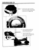
CLUTCH SYSTEM I STARTER ROPE REMOVAL NEVER START ENGINE WITH CLUTCH DRUM HOUSING ASSEMBLY REMOVED. IF YOU DO, THE CLUTCH SHOES CAN SEPARATE FROM HUB AND CAUSE SERIOUS INJURY. 1. Disconnect spark plug wire. On LC models remove top cover to disconnect sparkplug wire. For LC models remove switch wires from ignition coil at this time. I r .,. P ‘. I 1 2. 3. Remove the four screws holding clutch drum housing and starter assembly.
:LUTCHSYSTEM STARTER ROPE INSTALLATION NOTE: Always wear safety glasses when working on the starter assembly. 1. Place starter pulley back into the starter housing, making sure pulley interlocks with starter spring. 2. Reinstall starter pulley retaining tab(s). 3. Hand turn starter pulley 8 revolutions clockwise on 32 R models and counterclockwise on 26 RLC and LC models. 4. Turn the pulley counterclockwise two full revolutions on 32 R, clockwise on 26 LC, RLC and 32 RL. 5.
CLUTCH SYSTENl I 7. On RLC units, remove the starter assembly from the engine. On LC units, remove four 4mm screws securing starter housing assembly and remove starter. NOTE: Always wear safety glasses when working on starter assemblv repairs. DO NOT REMOVE THE PULLEY RETAINING TAB AND SCREW WITHOUT RELEASING SPRING TENSION. THE SPRING BENEATH THE PULLEY IS UNDER PRESSURE AND CAN COME OUT AND CAUSE SERIOUS INJURY. 8.
CYLINDER. PISTON &RING CAUTION THE MUFFLER IS HELD TO THE CYLINDER BY TWO SPRINGS. ALWAYSWEAR SAFETY GLASSES WHEN REMOVING MUFFLER RETAINING SPRINGS. CYLINDER & PISTON REPLACEMENT 1. Remove spark plug. ~~ I 2. On RLC units refer to crankshaft and reed valve replacement section. On LC units remove top cover. Remove muffler by releasing muffler retaining springs with pliers. ,,.-’” ““+4. Using a 5mm hex wrench part number 5025057-01 remove two cylinder head bolts.
CYLINDER. PISTON &RING RING REPLACEMENT 1. Refer to piston and cylinder replacement section to remove cylinder. 2. Once cylinder is removed ring can now be replaced. NOTE: Use caution when replacing the piston ring. Ring may break if overexpanded. 3. Remove old ring by ex~ your fingers enough to 4. Expand new ring only enough to slide it over top of piston into ring groove. Use caution not to scar piston when installing new piston ring. 5. The ring is located on the piston by a locating pin.
CRANKCASE REED VALVE REPLACEMENT 1. Remove engine from drive shaft and starter (see starter section 1 thru 8). 2. Remove top cover on LC models. 3. Remove carburetor (see throttle cable removal section 1 thru 5). ~ ~ ~ 4. Remove six 4mm hex head screws at back of carburetor area as shown. 5. Separate engine from back plate housing as shown. 6. Remove two phillips head screws retaining reed valve assembly. 7. Replace reed valve and reinstall reed valve back plate with Phillips head screws.
CRANKCAS u 8. Replace crankcase gasket and reinstal using steps 1 thru 6 in reverse. 9. Use steps lthru 5 in this section. 10. Remove cylinder and piston as outlined in cylinder and piston removal section. 11. Connecting rod bottom bearing protrudes out farther on one side. This side upon installation goes toward reed valve side. A — 11.5 Thread clutch retaining nut on crankshaft until it is flush with the top of crankshaft as shown. ~r 12. Remove flywheel. 13.
CRANKCASE — 14. Remove snap ring next to bearing with snap ring pliers. CRANKSHAFT REMOVAL 15. Reinstall clutch nut on crank and tap top of crankshaft with a soft hammer and remove crankshaft as shown. BEARING REPLACEMENT 16. If bearing replacement is necessary, use tool (# 5025082-01) to remove outer bearing (the inner bearing will come out with crankshaft), to remove inner bearing from crankshaft use a bearing puller. 17. Remove snap ring behind outer bearing if seal replacement is necessary.
CRANKCAS SEAL REPLACEMENT NOTE: Make sure inner snap ring locator is in place (between inner bearing and seal). The snap ring locks in its own groove. 18. Lubricate both bearings with bearing g ease. 19. Tap in inner bearing against snap ring ocator with service tool number 5025082-01. 20. Turn case over and tap in new seal against other side of inner snap ring locator. 21. Install outer snap ring that was removed in step 17 (located behind outer bearing). 22.
NOTES 38