I Operator Manual ney. RZ5424 ] 28982 of any ethanol (E1 Please read the operator's manual carefully and make sure you understand tf fictions before using the machine.
When this product is worn out and no longer used, it should be returned to the reseller or other party for recycling. To implement improvements, specifications and designs can be altered without prior notification. Note that no legal demands can be placed based on the information contained in these instructions. Use only original parts for repairs. The use of other parts voids the warranty. Do not modify or install non-standard equipment fo the unit without consent from the manufacturer.
CONTENTS INTRODUCTION Lo 5 Driving and Transport on Public Roads. SYMBOLS AND DES 7 SAFETY... 9 Safety Ir ions... a Personal Safety Equipment... Wt Slope Operation Gasoline... 18 General Maintenance 1 Towing. ” Spark Ares tor 1% Transport. CONTROLS Control Locations. Swerving Control Lever 18 Parking Brahe oon 19 Theodore Control 19 Blade § ignition Sweet Che Control Hour Meter Sei HUTS LIVEN Ll 21 Fuses Tracking Knob Fue Tank. ar Suet Shut Off Valve L238 Suiting Height Adjuster 23 Bypass Linkages.
WARNING! Failure to follow cautious operating practices can result in serious injury to the operator or other persons, The owner must understand these instructions, and must allow only trained persons who understand these instructions to operate the mower. Each person operating the mower must be of sound mind and body and must not be under the influence of any mind altering substance.
INTRODUCTION Congratulations Thank you for purchasing a Parnassus ride-on mower. This machine is built for superior efficiency to rapidly mow primarily large areas. A control panel easily accessible to the operator and a hydro static transmission regulated by steering controls both contribute to the machine's performance. This manual is a valuable document. Read the contents carefully before using or servicing the machine.
INTRODUCTION Good Service Zarathustra's products are sold only in specialized retail stores with complete service. This ensures that you as a customer receive only the best support and service. Before the product is delivered, the machine has, for example, been inspected and adjusted by your retailer. See the certificate in the Service Journal in this operator's manual.
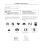
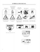
SYMBOLS AND DECALS These symbols ara found on the machine and in the operator's manual. Study them carefully so that you know what they mare.
SYMBOLS AND DECALS Saki off engine and ram ave key before performing Keep a safe Read Operator's distance from the Use on slopes no Manual or repair work machine greater than 10 No passengers Whole body exposure Severing of fingers Do not open or remove Careful backing up Careful going forward to thrown objects and toes safety shields while watch for other per watch for other people engine is running DANGER | | KEEP HANDS AND FEET AWAY Warring! Rotating blades, Ke away from the discharge deck Do not touch p
SAFETY Safety instructions These instructions are for your safety. Read them carefully. () WARNING! THIS CUTTING MACHINE 1S CAPABLE OF AMPUTATING HANDS AND FEET AND THROWING OBJECTS. FAILURE TO OBSERVE THE FOLLOWING SAFETY INSTRUCTIONS COULD RESULT IN SERIOUS INJURY OR DEATH. ( WARNING! This symbol means that important safety instructions need to be emphasized. It concerns your safety. General Operation * Read, understand, and follow all instructions an the machine and in the manual before starting.
SAFETY Disengage blades when not mowing. Shut off engine and wait for all parts to come to a complete stop before cleaning the machine, removing the grass catcher, or unclogging the discharge guard. Operate machine only in daylight or good artificial light Uo not operate the machine while under the influence of alcohol or drugs. Watch for traffic when operating near or crossing roadways. Use extra care when loading or unloading the machine into a trailer or truck.
SAFETY Personal Safety Equipment A WARNING! When using the machine, approved personal protective equipment (shown in Illustrations) shall be used. Personal protective equipment cannot eliminate the risk of injury but it will reduce the degree of injury if an accident does happen. Ask your retailer for help in choosing the right equipment. # Make sure halt you have first aid equipment close at hand when using the machine. + Never use the machine when barefoot.
SAFETY + Dona ry to stabilize the machine by putting a foot on the ground. » Do not mow near drop-offs, ditches. or embankments. The machine could suddenly roll over if a wheel is over the edge or if the edge caves in WARNING! CHILDREN CAN BE INJURED BY THIS EQUIPMENT. The American Academy of Pediatrics recommends that children be a minimum of 18 years of age before operating a riding lawn mower. Keep children out of the mowing area and in the watchful care of a responsible audit other than the operator.
SAFETY Safe Handling of Gasoline WARNING! The engine and the exhaust system become very hot during operation. There is risk for burns if touched. Allow engine and exhaust system to cool before refueling. To avoid personal injury or property damage, use extreme care in handling gasoline. Gasoline is extremely flammable and the vapors are explosive Extinguish all cigarettes, cigars, pipes, and other sources of ignition.
SAFETY General Maintenance ° Never operate machine in a closed area. Keep all nuts and bolts tight to be sure the equipment is In safe working condition Never tamper with safety devices. Check their proper operation regularly. Keep machine free of grass, leaves, or other debris buildup. Clean oil or fuel spillage and remove any fuel-sacked debris. Allow machine to cool before storing. If you strike a foreign object, stop and inspect the machine. Repair, if necessary, before restarting.
SAFETY Sparking can occur when working with the battery and the heavy cables of the starter circuit. This can cause battery explosion, fire or eye injury. Sparking in this circuit can not occur after the chassis cable {normally negative, black) is removed from the battery. WARNING! Avoid electrical sparking and its consequences by the following routines: * lase protective goggles.
SAFETY Transport The machine is heavy and can cause serious crushing injuries. Be extra cautious when iris loaded on or unloaded from a vehicle or trailer. Use an approved trailer to transport the machine. Activate the parking brake, tum off the fuel supply, and fasten the machine with approved fastening devices, such as bands, chains, or straps, when transporting. Oo not operate this making on public roadways. Check and abide by local traffic regulations before transporting the machine on any road.
CONTROLS This operator's manual describes the Husbandman driven hydraulic pumps. Using the left and right Zero Turn Rider. The rider is fitted with a four-stroke steering controls, the flow is regulated and thereby the overhead valve engine, direction and speed. Transmission from the engine is made via a belt Control Locations 1. Steering control levers 8. Seat adjustment lever 2. Parking brake 9. Blade switch 3. Tracking adjustment 10. Ignition switch 4. Shutterbug off valve 11. Throttle 5.
CONTROLS Steering Control Levers The making's speed and direction are continuously variable using the two steering controls. The steering controls can be moved forward or backward about a neutral position.
CONTROLS Parking Brake IMPORTANT INFORMATION The machine must be not be moving when engaging the parking brake. Always set the parking brake before dismounting. Release the parking brake before moving the mower. The parking brake fs found on the left of the machine.
CONTROLS ignition Switch The ignition switch is placed on the control panel and is used fo start and stop the engine. On models equipped with headlights. turn the key clockwise to ACCESSORY for headlight use. Choke Control The choke control is used for cold starts to provide the engine with a richer fuel mixture Far cold starts on medals with separate choke, the control should be puled up.
CONTROLS Seat Adjustment Lever The seat can be adjusted length ways. Wuhan making adjustments, the lever under the right side of the seats pulled up, after which the seat can be moved backward or forward. IMPORTANT INFORMATION Seat should not be adjusted while unit is in motion. Fuses Fuses are located on the left hand side of the machine. They are accessed by tilting the seat forward. They are flat pin fuses of the same type used in automobiles.
CONTROLS Fuel Tank Read the safety instructions before refusing. The machine has one fuel tank, just behind the console. The tank capacity is 3.5 gallons {13.25 liters). Regularly check the gas cap gasket for damage and keep the cap properly tightened The engine will run on a minimum of 85-octane unleaded gasoline (no oil mix). Environmentally adapted lateral gasoline can be used. See also Technical Data concerning ethanol fuel. Methanol fuel is not allowed. Do not use E85 alcohol based fuel.
CONTROLS Fuel Shut Off Valve The fuel shut off valve is located at the left rear of the seat. The valve is off when the handle tab is turned perpendicular to the ful line. IMPORTANT INFORMATION Always raise the deck to the highest position for transport. Cutting Height Adjuster To set the desired deck cutting height, press the release button and move the lever forward to the preset height pin and release the button. See Before Starting in the Operation section to change the cutting height.
OPERATION Read the Safety section and following pages. if you are unfamiliar with the machine. Training Due to unique steering capabilities. zero turn mowers are far more maneuverable than typical riding Mowers This section should be reviewed in its entirety prior to attempting to move the mower under its own power When first operating the mower or unit! becoming comfortable with controls. use a reduced throttle speed and reduced ground speed.
OPERATION Before Starting 1. Read the sections on Safety and Controls before starting the machine 2. Perform the dally maintenance before starting {see Maintenance Schedule in the Maintenance section), 3. Check that there is sufficient fuel in the fuel tank 4. Adjust the seat to the desired position. 5. Set the deck cutting height by inserting the fight pin into the desired cut height. Re secure the lift pin with the hairpin.
OPERATION Starting the Engine 1. Synthesis seat. 2. Raise the mower deck by pushing the release button on the top of the lifting lever. Pull the lifting lever backward to the locked (transport) position. 3. Activate the parking brake by pushing the release button in and pulling the lever fully upwards, 4. Disengage the mower blades by pressing the blade switch downwards.
OPERATION 5. Move the steering controls outward to the locked (outer) neutral position. 8. Move the throttle to the middies position. Set the throttle 7. If the engine is cold, the choke control should be puled up.
OPERATION 8. Press in and turn the ignition kay to the start position. IMPORTANT INFORMATION Do not run the starter for more than 5 seconds each time. If the engine does not start, wait approximately 10 seconds before retrying. Tur to the start position 9. When the engine starts. immediately release the ignition key back to the run position. Push the choke control in gradually when the engine has started.
OPERATION Weak Battery {) WARNING! Lead-acid batteries generate explosive gases. Keep sparks, flame and smoking materials away from batteries. Always wear eye protection when around batteries. IMPORTANT INFORMATION Your mower is equipped with a 12-volt negative grounded system. The other vehicle must also be a 12-volt negative grounded system. Do not use your mower to start other vehicles. if the battery Is too weak to start the engine, it should be recharged. (See Battery in the Maintenance section.
OPERATION Running 1. Release the parking brake by pushing the top release button in and moving the lever downward. NOTE: The mower is equipped with an operator presence system. When the engine is running, any attempt by the operator to leave the seat without first setting the parking brake will shut off the engine. 2. Move the steering controls inwards, out of the neutral position (N}. 3. Push the release button on the citing height lever and move lever {o the pin, release the button.
OPERATION Operating On Hills Read the Safety Instructions Driving on Slopes in the Safely section. WARNING! Do not drive up or down hills with slopes greater than 10 degrees. Do not drive across slopes. # The slowest speed possible should be used before starting up or down hills. + Avid stopping or changing speed on hills + If stopping is absolutely necessary. pull steering controls into the neutral position and push io the outside of the unit.
OPERATION Mowing Tips Observe and flag rocks and other fixed objects to avoid collisions. Begin with a high cutting height and reduce it until the desired mowing result is attained. The average lawn should be cut during the cool season and aver 3' (76 mm) during the hot months.
OPERATION Stopping the Engine 1. Move the throttle to the minimum position {tortoise symbol}. 2. Move the steering controls outward. 3. Disengage the mower deck by pressing the blade switch down. 4. Raise the mower deck by pressing the release button an the lever and pulling the lever upward to the transport position. 5. When the machine is standing still, activate the parking brake by pushing the lever release button and pulling the lever upward.
OPERATION Moving Machine By Hand When pushing or pulling the mower. engage the EZT bypass linkages. The EZT bypass linkages are located on the rear of the frame, below the rear engine guard. 1. Raise the deck into the highest cutting position. Engage the parking brake. 3. Pull the EZT bypass linkages up and out of the keyhole slots. Release the levers with the head outside the frame and held in the bypass position. 4, To reengage the EST's to drive, reverse the above procedure.
MAINTENANCE Maintenance Schedule The following is a list of maintenance procedures that must be performed on the machine. For those points not described in this manual, visit an authorized service workshop. An annual service carried out by an authorized service workshop is recommended to maintain your machine in the best possible condition and to ensure safe operation.
MAINTENANCE Daily At least Maintenance once interval each in hours MAINTENANCE Before After Y*%' 25 50 100 300 Check/adjust throttle cable " Check the condition of belts, belt pulleys ® @® Change the engine ofl © B B Replace the engine oil filter os B Clean/replace the spark plugs 5 Replace the fug filter ® ® Replace paper air filter ? 5 ow Check the caster wheels {every 200 hours) ® ® Replace the air cleaners foam per-filter # Bs Check/adjust the mower deck ® @ Check the engine valve clearance # Ld + Perfo
MAINTENANCE Battery Your mower is equipped with a maintenance free battery and does not need servicing. However, periodic charging of the battery with an automotive type battery charger will extend its life. . Keep battery and terminals clean. Keep battery bolts tight. See chart jor charging times. CAUTION! Always wear eye protection when around batteries. Cleaning battery and terminals Corrosion and dirt on the battery and terminals can cause the battery to lose power, Open the terminal access doors.
MAINTENANCE Safety System The making is equipped with a safety system that prevents starting or driving under the following conditions. The engine can only be started when: 1. The mower deck is disengaged. 2. The steering controls are in the outer, locked neutral position. 3. The parking brake is on. Make daily inspections to ensure that the safety system works by attempting to start the engine when one of the conditions Is not met. Change the conditions and try again.
MAINTENANCE Tire Pressures All tires should be at 18 psi / 103 kPa / 1 bar. Anti-scalp Rollers IMPORTANT INFORMATION Adjust anti-scalp rollers with the mower on a flat level surface. Anti-scalp rollers are properly adjusted when that are just slightly off of the ground when the deck is at the desired cutting height in the operating position. Anti scalp rollers then keep the deck in the proper position to help prevent scalping in mast terrain conditions.
MAINTENANCE V-belts Check every 100 hours of aeration. Check for severe cracking and large nicks. NOTE: The belt will show some small cracks in normal operation. The belts are not adjustable. Replace belts if they begin to slip from wear. Deck Belt Removal 1. Park on a level surface. Apply parking brake. Lower the deck into the lowest cutting position. Remove bolts from belt shields and remove shields. 4. Remove any dirt or grass that may have congratulated around the cutter housings and w ’ 1.
MAINTENANCE Cutting Blades To attain the best mowing effect. it is important that blades are well sharpened and not damaged. Replace blades that have been bent or cracked when hitting obstacles. Let the service workshop should decide whether the blade can be repaired/ground or must be replaced. Balance the blades after sharpening. Check the blade mounts WARNING! Blades are sharp. Protect your hands with gloves and/or wrap blades with a heavy cloth when handling.
MAINTENANCE Adjusting the Mower Deck Leveling deck Adjust the deck while the mower is on a level surface. Make sure the tires are Inflated to the correct pressure. See Technical Data / Transmission, If tires are under or over inflated, the deck cannot be properly adjusted. Raise the deck to the highest {transport} position. The deck should be adjusted slightly higher in the rear. NOTE: To insure accuracy of leveling procedure, mower deck drive belt must be installed prior to leveling deck. 1.
MAINTENANCE Caster Wheels Check Avery 200 hours. Check that wheels rotate freely. If wheels do not rotate freely take the unit to your dealer for service, Foam filled tires or solid tires will void the warranty. Removal and installation of caster wheel 1. Remove nut and caster bolt, 2. Pull the wheel out of the yoke and take care of the Spacers. 3. Install in reverse order. Tighten caster Holt. IMPORTANT INFORMATION DO NOT add any type of tire liner or foam fill material to the tires.
LUBRICATION Lubrication Schedule 12/12] 1/52 [1/365] 28h | 50h 1100th [200th |300h E 12/12 Every year Lubricate with grease gun Filter change © 1/52 Every Week Qil change Y Level cheek o 1/365 Every day General Remove the ignition key to prevent unintentional movements during lubrication. When lubricating with an oil can, i must be filled with engine cil When lubricating with grease, unless otherwise stated use a high grade molybdenum delphinium grease. For daily use.
LUBRICATION Wheel and Deck Perks Use only good quality bearing grease. Grease from well-known brand names {petrochemical companies. tee) usually maintains a good quality. Front Wheel Mount Lubricate 3-4 strokes with a grease gun on each set of wheel bearings. Front Wheel Bearings Lubricate 3-4 strokes with a grease gun on each set of wheel bearings IMPORTANT INFORMATION Use minimal lubrication and remove excess lubricant so that is does not come into contact with belts or belt pulley drive surfaces.
TROUBLESHOOTING Problem Cause Engine will not start + Blade switch is engaged. » Steering controls are not locked in the neutral position + Parking brake is not activated ® Battery is dead + Contamination in the carburetor or fuel line.
TROUBLESHOOTING Problem Cause Engine overheats + Clogged air intake or cooling fins * Engine overloaded = Poor ventilation around engine * Defective engine speed regulator = Too little or no oil in the engine * Contamination in the carburetor or fuel line.
STORAGE Winter Storage The making should be readied for storage al the end of the mowing season or if it will not be in use for longer than 30 days. Fuel allowed to stand for long periods of time (30 days or more) narc leave sticky residues that can plug the carburetor and disrupt engine function. Fuel stabilizers are an acceptable option as regards to the sticky residues that can scour during storage. Addie stabilizer to the fuel in the tank or in the storage container.
SCHEMATICS NOTES: 1. SEAT UNOCCUPIED 2, BRAKE SWITCH IN OFF POSITION 2. MOTION CONTROL LEVERS QUT 4.
TECHNICAL DATA Torque Specifications Engine crankshaft bolt 75 fib (100 Limy Standard 14" fasteners Sth (12 Nmy Deck pulley bolts 75 filbert (100 Nm} Standard * fasteners 18 fil {25 Nm} Lug nuts 75 ft fib (100 Nm) Standard 9" fasteners 33 ft/lb (44 Nm) Blade bolt 50 Hb (67 Nim Standard "fi" fasteners 52 fills (70 Nm) Standard 1%" fasteners 80 ffl (110 Nm) HEX HEAD CAP SCREWS The torque values sham should be used as a general guideline when specific torque values are not given U.S.
TECHNICAL DATA RZ5424 / 28982 Engine Manufacturer Kohl er Type Courage Fowler 24 hp 2 Lubrication Pressure with ail filter Fuel Min 87 octane unleaded (Max ethanol 10%, Max MTGE 15%) Fuel tank capacity 3.5 gallons / 13.25 liters Cooling Ar cooled Ar filter Standard Alternator 12v Starter Electric Transmission Transmission Hydro static trans axles Speed and direction controls Dual levers, foam gripped Speed forward 0-8.5 mph / 0-10.5 km/h Speed reverse 0-3.
CONFORMITY CERTIFICATES USA requirements Labels are placed on the engine and/or in the engine compartment stating that the machine will fulfill the requirements. This is also applicable to special requirements for any of the states, (California emission rules etc}. Do not remove any of these labels. Certificates can also be supplied with the machine at delivery or written in the Engine manual. Take care of them as they arg valuable documents.
SERVICE JOURNAL Action Date, mir reading, stamp, sign Delivery Service Charge the battery Adjust the tire pressure of all wheels to 15 PSI({1 bar) Mount the steering controls in the normal position Connect the contact box to the cable for the seat's safety switch Check that the right amount of oil is in the engine Adjust the position of the steering controls Fill with fuel and open the fuel shut off valve Start the engine Check that there is drive to both wheels Check the mower deck adjustment Check: The sa
SERVICE JOURNAL Action Date, mir reading, stamp, sign After the First 10 Hours Change engine oil 0 Action Date, mir reading, stamp, sign 25-Hour Service Check the fuel pump’s alr filter Sharpen/Replace mower blades if required Check the tire pressures Check battery with cables Lubricate according to lubrication chart Houseclean the engine's cooling alr intake Clean the air cleaners foam per-filter Lo Do
SERVICE JOURNAL Action Date, mtr reading, stamp, sign 50-Hour Service Perform the 25-hour service Replaceable the air cleaners paper filter cartridge {shorter intervals for dusty operating conditions) Change engine ofl Lubricate according to lubrication chart Check/adjust the parking brake doo oo Action Date, mir reading, stamp.
SERVICE JOURNAL Action Date, mir reading, stamp, sign 300-Hour Service Perform the 25-hour service Perform the 50-hour service Perform the 100-hour service Checklist the mower deck Clean the combustion chamber and grind the valve seats Check the engine valve clearance Replace the alr cleaners foam per-filtler google Action Date, mir reading, stamp, sign At Least Once Each Year Clean the engine's cooling alr intake (25 hours) Replace the air cleaners foam per-filter (300 hours) Replace the air filter's paper