322E 325E-X Operator's Manual Read through the Operator‘s manual carefully and understand the content before using the machine.
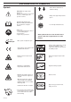
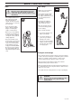
EXPLANATION OF SYMBOLS Symbols • Arrows which show limits for handle mounting. WARNING! The edger can be dangerous! Careless or incorrect use can result in serious or fatal injury to the operator or others. Read through the Operator's Manual carefully and understand the content before using the machine. Always use: • A protective helmet where there is a risk of falling objects. • Ear protection • Approved eye protection max 10000 rpm • Always wear approved protective gloves.
CONTENTS List of Contents Husqvarna AB has a policy of continuous product development and therefore reserves the right to modify the design and appearance of products without prior notice. EXPLANATION OF SYMBOLS Symbols ............................................................................... 2 CONTENTS List of Contents ...................................................................
SAFETY INSTRUCTIONS Personal protective equipment IMPORTANT INFORMATION • An edger used incorrectly or carelessly can become a dangerous tool, that can cause serious or fatal injury to the operator or others. It is extremely important that you read and understand the content of this manual. • When using an edger, personal protective equipment approved by the appropriate authorities must be used.
SAFETY INSTRUCTIONS 4. Vibration damping system Your machine is equipped with a vibration damping system, which is designed to give as vibration-free and comfortable use as possible. The use of incorrect cutting equipment increases the level of vibration. The machine’s vibration damping system reduces the transfer of vibrations between the engine unit/cutting equipment and the machine’s handle unit.
SAFETY INSTRUCTIONS Control, maintenance and service of the machine’s safety equipment 3. Cutting attachment guard • Ensure that the guard is undamaged and is not cracked. IMPORTANT INFORMATION • All service and repairs to the machine require special training. • This applies especially to the machine’s safety equipment. If the machine does not meet any of the controls listed below you should contact your service workshop.
SAFETY INSTRUCTIONS 6. Cutting equipment 7. Locking nut The two basic rules: • Protect your hand from injury when assembling, use the blade guard as protection when tightening with a socket spanner. Tighten the nut by turning against the direction of rotation. Loosen the nut by turning in the direction of rotation. (NOTE! the nut has a left-hand thread). 1. Only use the cutting equipment we recommend! See chapter “Technical data”. 2.
SAFETY INSTRUCTIONS General safety instructions IMPORTANT INFORMATION • The machine is only designed for cutting the edges of lawns. • The only accessories to be used with the engine unit as a drive source are the cutting units we recommend in the chapter “Technical data”. • The operator is responsible for accidents and the risk people and property are exposed to. Safety instructions before starting work • Inspect the working area.
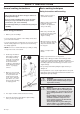
SAFETY INSTRUCTIONS Start ! Fuel safety WARNING! When the engine starts with the choke lever in the choke or starter throttle position the cutting tool (blade or trimmer) starts to rotate immediately. • The complete clutch cover with shaft must be fitted before the machine is started, otherwise the clutch can become loose and cause personal injury. • Never start the machine indoors. Bear in mind the dangers of inhaling the engine’s exhaust fumes.
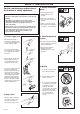
SAFETY INSTRUCTIONS General working instructions IMPORTANT INFORMATION • This section takes up the basic safety precautions for working with the edger. • If you encounter a situation where you are uncertain how to proceed you should ask an expert. Contact your dealer or your service workshop. • Avoid all usage which you consider to be beyond your capability. Basic safety precautions 1.
SAFETY INSTRUCTIONS Safety instructions after completing work • Ensure the blade has stopped before cleaning, carrying out repairs or an inspection. Remove the spark plug cable from the spark plug. • Wear heavy-duty gloves when carrying out repairs on the edger. • Store the machine out of reach of children. • Only use original spare parts with repair.
WHAT IS WHAT? 1 4 21 4 20 1 26 24 What is what on the edger? 1. Blade 14. Air purge 2. Grease filler cap 15. Air filter cover 3. Angle gear 16. Clutch cover 4. Blade guard 17. Handlebar adjustment 5. Shaft 18. Locking nut 6. Loop handlebar 19. Support flange 7. Throttle 20. Drive disc 8. Stop switch 21. Locking handle 9. Throttle trigger lock 22. Socket spanner 10. Cylinder cover 23. Operator's Manual 11. Starter handle 24. Locking pin 12. Fuel tank 25. Allen key 13.
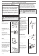
ASSEMBLY Assembling the loop handlebar • Position the handle on the shaft. Note that the handle must be mounted below the arrow on the shaft. Assembling the blade Fit the blade as follows: 1. Fit the drive disc (A) on the outgoing shaft. Make sure that the edge that fits in the hole of the blade is facing outward. 2. Block the blade rotation by inserting locking pin in the hole behind the blade guard engaging it in the corresponding hole in the drive disc. 3. Fit the blade (B) on the drive disc. 4.
FUEL HANDLING Fuel mixture NOTE! The edger is fitted with two-stroke engines and must always be run on a mixture of petrol and two-stroke oil. To ensure the correct mixture proportions it is important to measure the quantity of oil accurately. When mixing small amounts of fuel small discrepancies in the amount of oil have a great bearing on the proportions of the fuel mixture. ! WARNING! Always provide good ventilation when handling fuel.
START AND STOP Control before starting For reasons of safety follow these recommendations! • Check that the support flange is not cracked due to fatigue or due to being tightened too much. Discard the support flange if it is cracked. • Ensure that the nut has not lost its tightening capacity. The nut lock shall have a locking torque of at least l.5 Nm. The nut’s tightening torque shall be 35-50 Nm. • Check that the blade and blade guard are not damaged or cracked.
MAINTENANCE Carburettor Your Husqvarna product has been designed and manufactured to specifications that reduce harmful emissions. After your unit has been run 8-10 tanks of fuel the engine has broken in. To ensure that your unit is at peak performance and producing the least amount of harmful emissions after break in, have your authorized servicing dealer, who has a revolution counter at his disposal, to adjust your carburettor for optimum operating conditions.
MAINTENANCE Final setting of the idling speed T Correctly adjusted carburettor A correctly adjusted carburettor means that the machine accelerates without hesitation and the machine 4-cycles a little at max speed. Furthermore, the cutting attachment must not rotate/move at idling. A too lean adjusted low speed needle L may cause starting difficulties and bad acceleration. A too lean adjusted high speed needle H gives lower power = less capacity, bad acceleration and/or damage to the engine.
MAINTENANCE Muffler with catalytic converter Cooling system A muffler fitted with a catalytic converter reduces the extent of the following substances in the exhaust fumes: To maintain as low an operating temperature as possible the engine is equipped with a cooling system. • Hydrocarbons (HC). Some hydrocarbons in gasoline and the exhaust are carcinogenic. • Nitric oxides (NO). Irritating for the breathing air-ways. • Aldehydes.
MAINTENANCE Air filter Lubricating the flexible drive axle The air filter should be cleaned regularly removing dust and dirt to avoid: • carburettor malfunction • starting problems • reduced engine power • unnecessary wear to engine parts • abnormal fuel consumption Inside the edger‘s drive shaft is a flexible drive axle. The flexible drive axle should be regularly lubricated after 30 hours of operation. Loosen the two screws on the angle gear and remove it.
MAINTENANCE Maintenance schedule Weekly maintenance Below follows some general maintenance instructions. If you need further information please contact your service workshop. 1. Check the starter, the starter cord and the return spring. 2. Make sure that the vibration damping elements are not damaged. 1 Daily maintenance 1. Clean the outside of the machine. 2. Make sure the throttle trigger lock and the throttle function correctly from a safety point of view. 3. 4. 5. 6. 7. 1 3 2 3.
MAINTENANCE Monthly maintenance I. Clean the fuel tank using petrol. 2. Clean the outside of the carburettor and the area surrounding it. 3. 4. Clean the fan wheel and the area around it. 1 2 3 Check the fuel filter and the fuel pipe, replace if necessary. 5. Check all cables and connections. 6. Check the clutch, clutch springs and the clutch drum with regard to wear. Replace if necessary. 7. Change the spark plug.
TECHNICAL DATA Technical data 322E 325E-X 1,33/21,7 1,26/32 1,06/27 11 000-11 700 2 700 8 300 0,7 kW/9 000 rpm Yes Yes 1,50/24,5 1,34/34 1,06/27 11 000-11 700 2 700 8 300 0,9 kW/9 000 rpm Yes Yes Walbro MB 21 Champion RCJ 7Y 0,02/0,5 Walbro MB 21 Champion RCJ 7Y 0,02/0,5 Zama C1Q 1,06/0,5 Zama C1Q 1,06/0,5 11,0/5,0 11,2/5,1 96 96 102 102 2,0/3,5 5,7/6,0 1,4/2,6 6,0/4,4 531 00 40-44 503 84 65-01 531 00 40-44 503 84 65-01 Engine Cylinder capacity, cu.
EU declaration of conformity (Only applies to Europe) (Directive 98/37/EC, Annex II, A) We, Husqvarna AB, S-561 82 Huskvarna, Sweden, tel.
´*2£T¶6N¨ 1999W37