Operator’s manual (EPA) 324LX-series 324LDX-series Please read the operator’s manual carefully and make sure you understand the instructions before using the machine.
KEY TO SYMBOLS Symbols Only use non-metallic, flexible cutting attachments, i.e. trimmer heads with trimmer cord. WARNING! Clearing saws, brushcutters and trimmers can be dangerous! Careless or incorrect use can result in serious or fatal injury to the operator or others. Other symbols/decals on the machine refer to special certification requirements for certain markets. Please read the operator’s manual carefully and make sure you understand the instructions before using the machine.
CONTENTS Contents KEY TO SYMBOLS Symbols ....................................................................... CONTENTS Contents ...................................................................... Note the following before starting: ................................ SAFETY INSTRUCTIONS Personal protective equipment ..................................... Machine′s safety equipment ........................................ Checking, maintaining and servicing the machine′s safety equipment ..................
SAFETY INSTRUCTIONS Personal protective equipment IMPORTANT! You must use approved personal protective equipment whenever you use the machine. Personal protective equipment cannot eliminate the risk of injury but it will reduce the degree of injury if an accident does happen. Ask your dealer for help in choosing the right equipment. ! WARNING! Listen out for warning signals or shouts when you are wearing hearing protection. Always remove your hearing protection as soon as the engine stops.
SAFETY INSTRUCTIONS ! WARNING! Never use a cutting attachment without an approved guard. See the chapter on Technical data. If an incorrect or faulty guard is fitted this can cause serious personal injury. Vibration damping system For mufflers it is very important that you follow the instructions on checking, maintaining and servicing your machine. See instructions under the heading Checking, maintaining and servicing the machine’s safety equipment.
SAFETY INSTRUCTIONS Checking, maintaining and servicing the machine′s safety equipment IMPORTANT! All servicing and repair work on the machine requires special training. This is especially true of the machine′s safety equipment. If your machine fails any of the checks described below you must contact your service agent. When you buy any of our products we guarantee the availability of professional repairs and service.
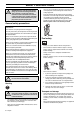
SAFETY INSTRUCTIONS • Regularly check that the muffler is securely attached to the machine. CAUTION! The nylon lining inside the locking nut must not be so worn that you can turn it by hand. The lining should offer a resistance of at least 1.5 Nm. The nut should be replaced after it has been put on approx. 10 times. ! • The muffler on your machine is equipped with a spark arrestor mesh, this should be cleaned regularly. A blocked mesh will cause the engine to overheat and may lead to serious damage.
SAFETY INSTRUCTIONS ! WARNING! Always stop the engine before doing any work on the cutting attachment. This continues to rotate even after the throttle has been released. Ensure that the cutting attachment has stopped completely and disconnect the HT lead from the spark plug before you start to work on it. • Observe your surroundings and make sure that there is no risk of people or animals coming into contact with the cutting equipment.
SAFETY INSTRUCTIONS • When storing the machine for long periods the fuel tank must be emptied. Contact your local gas station to find out where to dispose of excess fuel. 4 Switch off the engine before moving to another area. Fit the transport guard before carrying or transporting the equipment any distance. • The transport guard must always be fitted to the cutting attachment when the machine is being transported or in storage.
SAFETY INSTRUCTIONS • When trimming and clearing you should use less than full throttle so that the cord lasts longer and to reduce the wear on the trimmer head. Cutting • The trimmer is ideal for cutting grass that is difficult to reach using a normal lawn mower. Keep the cord parallel to the ground when cutting. Avoid pressing the trimmer head against the ground as this can ruin the lawn and damage the tool.
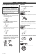
WHAT IS WHAT? LD X What is what? 1 Trimmer head 12 Air purge 2 Bevel gear 13 Fuel tank 3 Grease filler cap, bevel gear 14 Choke control 4 Cutting attachment guard 15 Air filter cover 5 Shaft 16 Handle adjustment 6 Loop handle 17 Drive disc 7 Stop switch 18 Allen key 8 Throttle control 19 Locking pin 9 Throttle lock 20 Shaft coupling 10 Cylinder cover 21 Operator’s manual (EPA) 11 Starter handle English – 11
ASSEMBLY Fitting the loop handle Dismantling: • • Undo the knob (at least three turns). • Push the knob towards the coupling. • Carefully twist the lower half of the shaft to unlock it. • Hold both parts of the shaft and pull the lower part of the shaft out of the coupling. Clip the loop handle onto the shaft. Note that the loop handle must be fitted between the arrows on the shaft. • Slide the spacer into the slot in the loop handle. • Fit the nut, knob and screw. Do not overtighten.
ASSEMBLY • Fit the nut (G). The nut must be tightened to a torque of 35-50 Nm (3.5-5 kpm). Use the socket spanner in the tool kit. Hold the shaft of the spanner as close to the blade guard as possible. To tighten the nut, turn the spanner in the opposite direction to the direction of rotation (Caution! left-hand thread). Fitting other guards and cutting attachments • Fit the correct trimmer guard (A) for use with the trimmer head.
FUEL HANDLING Fuel When the oil level is low, top up using engine oil to the edge of the oil refill hole. CAUTION! The machine is equipped with a four-stroke engine. Make sure that there is always sufficient oil in the oil tank. ! WARNING! Always ensure there is adequate ventilation when handling fuel. The catalytic converter muffler gets very hot during and after use. This also applies during idling. Be aware of the fire hazard, especially when working near flammable substances and/or vapours.
STARTING AND STOPPING Check before starting Cold engine Ignition: Set the stop switch to the start position. • Check that the support flange is not cracked due to fatigue or due to being tightened too much. Discard the support flange if it is cracked. Choke: Set the choke control in the choke position. • • Ensure the locking nut has not lost its captive force. The nut lock should have a locking force of at least 1.5 Nm. The tightening torque of the locking nut should be 35-50 Nm.
STARTING AND STOPPING Starting ! WARNING! When the engine is started with the choke in either the choke or start throttle positions the cutting attachment will start to rotate immediately. Hold the body of the machine on the ground using your left hand (CAUTION! Not with your foot!). Grip the starter handle, slowly pull out the cord with your right hand until you feel some resistance (the starter pawls grip), now quickly and powerfully pull the cord.
MAINTENANCE Carburettor ! WARNING! The complete clutch cover and shaft must be fitted before the machine is started, otherwise the clutch can come loose and cause personal injury. The muffler on your machine is equipped with a spark arrestor mesh, this should be cleaned regularly. A blocked mesh will cause the engine to overheat and may lead to serious damage. Function CAUTION! Never use a machine with a defective muffler. • • The carburettor governs the engine’s speed via the throttle control.
MAINTENANCE If the machine is low on power, difficult to start or runs poorly at idle speed: always check the spark plug first before taking any further action. If the spark plug is dirty, clean it and check that the electrode gap is 0,6-0,7 mm. The spark plug should be replaced after about a month in operation or earlier if necessary. Cleaning the air filter CAUTION! Always use the recommended spark plug type! Use of the wrong spark plug can damage the piston/cylinder.
MAINTENANCE CAUTION! Use only HUSQVARNA replacement parts. Use of other brands of replacement parts can cause damage to your unit or injury to the operator or others. Your warranty does not cover damage or liability caused by the use of accessories and/or attachments not specifically recommended by HUSQVARNA. Monthly maintenance • Clean the fuel tank. • Clean the outside of the carburettor and the space around it. • Check fuel hose for cracks or other damage. Change if necessary.
TECHNICAL DATA Technical data 324Lx 324LDx 1,53/25,0 1,53/25,0 Engine Cylinder volume, cu.in/cm3 Cylinder bore, inch/mm 1,38/35 1,38/35 Stroke, inch/mm 1,03/26 1,03/26 Idle speed, rpm 3100 3100 Recommended max. speed, rpm 11000 11000 Speed of output shaft, rpm 8300 8300 Max. engine output, acc.
FEDERAL EMISSION CONTROL WARRANTY STATEMENT YOUR WARRANTY RIGHTS AND OBLIGATIONS The EPA (The US Environmental Protection Agency), Environment Canada and Husqvarna Forest & Garden are pleased to explain the emissions control system warranty on your 2001 and later small nonroad engine. In U.S. and Canada, new small nonroad engines must be designed, built and equipped to meet the federal stringent anti-smog standards.
Super Auto II Super Auto II 1" 1 2 3 4 2,4 mm .
S35 2 3 2,4-2,7 mm .095-.
S35 3 2 2,4-2,7 mm .095-.
T35 2 3 2,4-2,7 mm .095-.
1140237-95 ´®z+H7o¶5p¨ ´®z+H7o¶5p¨ 2004-03-31