Operator's manual (EPA) 323P4 325P4X-SERIES 325P5X-SERIES Please read these instructions carefully and make sure you understand them before using the machine.
SYMBOL EXPLANATION Symbols WARNING! This machine can be dangerous. Careless or incorrect use can result in serious or fatal injury to the operator or others. • Always wear approved protective gloves. • Use anti-slip and stable boots. Read through the Operator‘s Manual carefully and understand the content before using the machine.
CONTENTS Husqvarna AB has a policy of continuous product development and therefore reserves the right to modify the design and appearance of products without prior notice. Maintenance, replacement, or repair of the emission control devices and systems may be performed by any nonroad engine repair establishment or individual. ! WARNING! Under no circumstances may the design of the machine be modified without the permission of the manufacturer. Always use genuine accessories.
SAFETY INSTRUCTIONS Personal protective equipment IMPORTANT INFORMATION • If used incorrectly or carelessly this machine can become a dangerous tool that can cause serious or fatal injury to the operator or others. It is extremely important that you read and understand the content of this manual. • When using the machine, personal protective equipment approved by the appropriate authorities must be used. Personal protective equipment does not eliminate the risk of accidents.
SAFETY INSTRUCTIONS 3. Vibration damping system Your machine is equipped with a vibration damping system, which is designed to give as vibration-free and comfortable use as possible. The machine’s vibration damping system reduces the transfer of vibrations between the engine unit/ cutting equipment and the machine’s handle unit. ! WARNING! Over exposure to vibrations can result in blood-vessel or nerve injury to persons suffering with blood circulation problems.
SAFETY INSTRUCTIONS Inspecting, maintaining and servicing machine safety equipment IMPORTANT INFORMATION • All service and repairs to the machine require special training. 2. Stop switch • Start the engine and make sure that the engine stops when the stop switch is moved to the stop position. • This applies especially to the machine‘s safety equipment. If the machine does not meet any of the controls listed below you should contact your service workshop.
SAFETY INSTRUCTIONS 5. Cutting equipment This section describes how through correct maintenance and through using the right type of cutting equipment you can: • Obtain maximum cutting capacity. • Increase the service life of the cutting equipment. 1 Check the cutting equipment with regard to damage and crack formation. Damaged cutting equipment should always be replaced. 2 Only use cutting equipment recommended by us! See the ”Technical data” section.
SAFETY INSTRUCTIONS Saw chain FILE POSITION • Saw chain pitch (inches) Spacing between drive links. • Drive link width (mm/ inches). • Number of drive links. ROUND FILE DIAMETER FILE DEPTH 1 5 Sharpening your chain and adjusting raker clearance ! WARNING! The risk of kickback is increased with a badly sharpened chain! A. General information on sharpening cutting teeth • Never use a blunt chain.
SAFETY INSTRUCTIONS C. General advice on setting raker clearance B. Sharpening cutting tooth To sharpen cutting teeth you will need a ROUND FILE and a FILE GAUGE. • When you sharpen the cutting teeth you reduce the RAKER CLEARANCE (cutting depth). To maintain cutting performance you must file back the raker teeth to the recommended height. 1. Check that the chain is correctly tensioned. A slack chain is difficult to sharpen correctly. 2.
SAFETY INSTRUCTIONS D. Adjusting raker clearance 1. Undo the bar nut. • When correction of the raker clearance is made the teeth must be newly sharpened. We recommend that you adjust the raker clearance every third time you sharpen the chain. NOTE! This recommendation assumes that the length of the cutting teeth is not reduced excessively. 2. Tension the chain by turning the chain tensioning screw clockwise using the combination spanner. Tighten the chain until it no longer hangs slack beneath the bar.
SAFETY INSTRUCTIONS Checking wear on cutting equipment C. Checking chain lubrication A. Saw chain • Check the chain lubrication each time you refuel. Aim the tip of the saw at a light coloured surface about 20 cm away. After 1 minute running at 3/4 throttle you should see a distinct line of oil on the light surface. Check the saw chain daily for: • Visible cracks in rivets and links. • Whether the chain is stiff. • Whether rivets and links are badly worn.
SAFETY INSTRUCTIONS General safety instructions IMPORTANT INFORMATION • The machine is only designed for tree pruning. • The only accessories to be used with the engine unit as a drive source are the cutting units we recommend in the chapter “Technical data“. • Never use the machine if you are tired, if you have consumed alcohol, or if you are taking medicines that can affect your sight, your judgement or the control of your body. • Use personal protective equipment.
SAFETY INSTRUCTIONS Safety instructions when using the machine ! WARNING! The machine can cause serious injury. Read the safety instructions carefully. Learn how to use the machine. Protective instructions while working • Always ensure you have a safe and firm working position. • Always use both hands to hold the machine. Hold the machine on the side of the body. • Use your right hand to operate the throttle. ! WARNING! Cutting tool. Do not touch the tool without first switching off the engine.
SAFETY INSTRUCTIONS Protective instructions when work is completed • The transport guard should always be fitted to the cuttingequipment when the machine is not in use. • Ensure the cuttingequipment has stopped and remove the spark plug cable from the spark plug before carrying out cleaning, repairs or an inspection. • Always wear heavy duty gloves when repairing the chain. The cuttingequipment is extremely sharp and can easily causes cuts. Observe great care when working close to overhead power lines.
SAFETY INSTRUCTIONS • Use the stop at the base of the bar to provide support during cutting. This will help prevent the cutting equipment from jumping on the branch. • Make an initial cut on the underside of the branch before cutting through the branch from above. This will prevent tearing of the bark, which could lead to slow healing and cause permanent damage to the tree. The first cut should not be deeper than 1/3 of the branch thickness to prevent jamming.
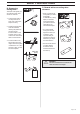
WHAT IS WHAT? 22 24 31 23 1 2 21 19 18 6 8 5 10 9 11 17 16 4 7 12 14 15 25 20 13 3 29 26 23 28 27 What is what on the machine? 1. 2. 3. 4. 5. 6. 7. 8. 9. 10. 11. 12. 13. 14. 15. Lubricant filler hole Bevel gearbox Chain lubrication adjustment screw (B) Chain lubrication locking screw (A) Shaft Front handle Throttle control Stop switch Throttle lock Hook for harness Cylinder cover Starter handle Fuel tank Choke control Fuel pump 16 – English 16. Air filter cover 17. Clutch cover 18.
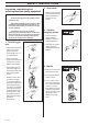
ASSEMBLY Fitting the cutting head • The chain is correctly tensioned when there is no slack on the underside of the bar, but it can still be turned easily by hand. Hold up the bar tip and tighten the bar nuts with the combination wrench. • Fit the cutting head on the shaft so that the screw (A) is aligned with the hole in the shaft as shown. • Tighten screw A. B • When fitting a new chain, the chain tension has to be checked frequently until the chain is run-in. Check the chain tension regularly.
ASSEMBLY Assembling and dismantling the two-part shaft (325P5) Assembling: • Make sure the handle is loose. • Guide the cut-out on the lower section of the shaft into the coupling‘s locking plate on the upper section of the shaft. The sections are then locked together. • Tighten the handle. Dismantling • Undo the handle (at least three turns). • Press the handle towards the coupling. • Carefully twist the lower section out of the lock.
FUEL HANDLING Fuel mixture NOTE! The machine is fitted with a two-stroke engine and must always be run on a mixture of gasoline and two-stroke oil. It is important to measure the quantity of oil accurately, to ensure the correct mixture ratio. Small discrepancies in the amount of oil have a great bearing on the proportions of the fuel mixture when mixing small amounts of fuel. ! WARNING! Always provide good ventilation when handling fuel.
START AND STOP Control before starting • Inspect the working area. Remove objects that can be thrown. • Check the cuttingequipment. Never use blunt, cracked or damaged equipment. • Check that the machine is in full working order. Check that all nuts and bolts are tightened correctly. • Make sure the chain is always well lubricated. • Ensure the cuttingequipment always stop when the engine is idling. • Only use the machine for what it is intended for.
MAINTENANCE Carburetor Your Husqvarna product has been designed and manufactured to specifications that reduce harmful emissions. After your unit has been run 8-10 tanks of fuel the engine has broken in. To ensure that your unit is at peak performance and producing the least amount of harmful emissions after break in, have your authorized servicing dealer, who has a revolution counter at his disposal, to adjust your carburetor for optimum operating conditions.
MAINTENANCE Final setting of the idling speed T Correctly adjusted carburetor Adjust the idling speed with the screw T, if it is necessary to readjust. First turn the idle speed adjusting screw T clockwise until the cuttingeqipment starts to rotate/ move. Then turn, counter-clockwise until the cuttingequipment stops. A correctly adjusted idle speed setting occurs when the engine runs smoothly in every position. It should also be good margin to the rpm when the cuttingequipment starts to rotate/move.
MAINTENANCE Muffler Cooling system NOTE! Some mufflers are fitted with a catalytic converter. See “Technical data” to see whether your machine is fitted with a catalytic converter. To maintain as low operating temperature as possible the engine is equipped with a cooling system. The cooling system consists of: 1. An air intake on the starter unit. The muffler is designed to dampen the noise level and to direct the exhaust fumes away from the user.
MAINTENANCE Air filter The air filter should be cleaned regularly removing dust and dirt to avoid: • carburetor malfunction • starting problems • reduced engine power • unnecessary wear to engine parts • abnormal fuel consumption Clean the filter after every 25 hours or more regularly if operating conditions are exceptionally dusty. Cleaning the air filter Dismantle the air filter cover and remove the air filter. Wash in clean, warm soapy water. Ensure that the filter is dry before refitting.
TECHNICAL DATA Technical data 323P4 325P4 325P5 Engine Displacement, cu. in/cm3 Cylinder bore, inch/mm Stroke length, inch/mm Recommended max. speed, rpm Idling speed, rpm Max. engine output, acc.
TECHNICAL DATA Bar and chain combinations The following combinations are CE approved. Bar Chain Length, inches Pitch, inches Max.
EMISSION CONTROL WARRANTY STATEMENT YOUR WARRANTY RIGHTS AND OBLIGATIONS The EPA (The US Environmental Protection Agency), Environment Canada and Husqvarna Forest & Garden are pleased to explain the emissions control system warranty on your 2001 and later small nonroad engine. In U.S. and Canada, new small nonroad engines must be designed, built and equipped to meet the federal stringent anti-smog standards.
114 00 84-95 ´+H(Q¶5,¨ 2002W22