Operator’s manual (CARB II, EPA II) 326P4 326P5X-series Please read the operator’s manual carefully and make sure you understand the instructions before using the machine.
KEY TO SYMBOLS Symbols Other symbols/decals on the machine refer to special certification requirements for certain markets. WARNING! The machine can be a dangerous tool if used incorrectly or carelessly, which can cause serious or fatal injury to the operator or others. Switch off the engine by moving the stop switch to the STOP position before carrying out any checks or maintenance. Please read the operator’s manual carefully and make sure you understand the instructions before using the machine.
CONTENTS Contents KEY TO SYMBOLS Symbols ....................................................................... CONTENTS Contents ...................................................................... Note the following before starting: ................................ SAFETY INSTRUCTIONS Personal protective equipment ..................................... Machine′s safety equipment ........................................ Checking, maintaining and servicing the machine′s safety equipment ..................
SAFETY INSTRUCTIONS Personal protective equipment IMPORTANT INFORMATION The machine can be a dangerous tool if used incorrectly or carelessly, which can cause serious or fatal injury to the operator or others. Please read the operator’s manual carefully and make sure you understand the instructions before using the machine. You must wear approved protective equipment whenever you use the machine.
SAFETY INSTRUCTIONS The machine′s vibration damping system reduces the transfer of vibration between the engine unit/cutting equipment and the machine′s handle unit. ! WARNING! Engine exhaust fumes contain carbon monoxide, which can cause carbon monoxide poisoning. For this reason you should not start or run the machine indoors, or anywhere that is poorly ventilated. The exhaust fumes from the engine are hot and may contain sparks which can start a fire.
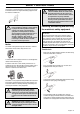
SAFETY INSTRUCTIONS in the idle position then the carburettor idle setting must be checked. See instructions under the heading Maintenance. Never use a muffler with a defective spark arrestor mesh. Cutting equipment Stop switch • Start the engine and make sure the engine stops when you move the stop switch to the stop setting.
SAFETY INSTRUCTIONS • Keep cutting equipment well lubricated and properly maintained! A poorly lubricated chain is more likely to break and lead to increased wear on the bar, chain and drive sprocket. ! ! WARNING! Never use a machine with faulty safety equipment. The machine’s safety equipment must be checked and maintained as described in this section. If your machine fails any of these checks contact your service agent to get it repaired.
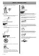
SAFETY INSTRUCTIONS • The cutting part of the chain is called the cutting link and this consists of a cutting tooth (A) and the raker lip (B). The cutting depth is determined by the difference in height between the two. A • It is very difficult to sharpen a chain correctly without the right equipment. We recommend that you use our file gauge. This will help you obtain the maximum kickback reduction and cutting performance from your chain.
SAFETY INSTRUCTIONS • File all the teeth to the same length. When the length of the cutting teeth is reduced to 4 mm (0.16") the chain is worn out and should be replaced. General advice on setting raker clearance • • • • Place the file over the part of the lip that protrudes through the gauge and file off the excess. The clearance is correct when you no longer feel any resistance as you draw the file over the gauge.
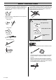
SAFETY INSTRUCTIONS - Use the combination spanner to tighten the blade nut while holding up the tip of the bar. Check that you can pull the saw chain round freely by hand. Checking chain lubrication • Check the chain lubrication each time you refuel. Aim the tip of the bar at a light coloured surface about 20 cm (8 inches) away. After 1 minute running at 3/4 throttle you should see a distinct line of oil on the light surface.
SAFETY INSTRUCTIONS • Whether rivets and links are badly worn. • We recommend you compare the existing chain with a new chain to decide how badly the existing chain is worn. When the length of the cutting teeth has worn down to only 4 mm the chain must be replaced. To prolong the life of the bar you should turn it over daily. ! WARNING! A faulty cutting attachment may increase the risk of accidents. General safety precautions Important The machine is only designed for cutting branches and twigs.
SAFETY INSTRUCTIONS • Place the machine on the ground, ensure the cutting attachment is clear of twigs and stones. Hold the body of the machine on the ground using your left hand (CAUTION! Not with your foot). Then grip the starter handle with your right hand and pull the starter cord. • The transport guard must always be fitted to the cutting attachment when the machine is being transported or in storage. ! WARNING! Take care when handling fuel.
SAFETY INSTRUCTIONS Safety instructions while working Safety instructions after completing work • Always ensure you have a safe and stable working position • The transport guard should always be fitted to the cutting attachment when the machine is not in use. • Always use both hands to hold the machine. Hold the machine at the side of your body. • Make sure the cutting attachment has stopped before cleaning, carrying out repairs or an inspection. Disconnect the HT lead from the spark plug.
SAFETY INSTRUCTIONS WARNING! This machine is not electrically insulated. If the machine touches or comes close to high-voltage power lines it could lead to death or serious bodily injury. Electricity can jump from one point to another by arcing. The higher the voltage, the greater the distance electricity can jump. Electricity can also travel through branches and other objects, especially if they are wet.
WHAT IS WHAT? 22 24 31 30 23 1 32 2 21 19 18 6 8 5 10 9 11 17 16 4 7 12 14 15 25 20 13 3 29 26 23 28 27 What is what? 1 Grease filler cap 17 Clutch cover 2 Bevel gear 18 Protective guard for saw chain 3 Chain lubrication adjustment screw (B) 19 Bar nut 4 Chain lubrication locking screw (A) 20 Chain tensioning screw 5 Shaft 21 Chain 6 Front handle 22 Bar 7 Throttle control 23 Chain oil tank 8 Stop switch 24 Filling with chain oil 9 Throttle lock 25 Operator’s ma
ASSEMBLY Fitting the cutting head • Fit the cutting head on the shaft so that the screw (A) is aligned with the hole in the shaft as shown. • Tighten screw A. • Tighten screw B. B A • The chain is correctly tensioned when there is no slack on the underside of the bar, and it can still be turned easily by hand. Tighten the bar nut with the combination spanner while holding up the tip of the bar. • When fitting a new chain, the chain tension has to be checked frequently until the chain is run-in.
ASSEMBLY Assembling and dismantling the two-piece shaft (325P5) Assembly: • Make sure the knob is loose. • Align the cut-out in the upper shaft with the coupling’s lock plate on the lower shaft. The parts then lock together. • Tighten the knob. Dismantling: Undo the knob (at least three turns). • Push the knob towards the coupling. • Carefully twist the upper shaft to unlock it. • Hold both parts of the shaft and pull the upper shaft out of the coupling.
FUEL HANDLING Fuel Mixing CAUTION! The machine is equipped with a two-stroke engine and must always been run using a mixture of gasoline and two-stroke engine oil. It is important to accurately measure the amount of oil to be mixed to ensure that the correct mixture is obtained. When mixing small amounts of fuel, even small inaccuracies can drastically affect the ratio of the mixture. • Always mix the gasoline and oil in a clean container intended for fuel.
STARTING AND STOPPING Check before starting Air purge: Press the air purge diaphragm repeatedly until fuel begins to fill the diaphragm. The diaphragm need not be completely filled. Warm engine • Inspect the working area. Remove any objects that could be thrown out. • Check the cutting attachment. Never use blunt, cracked or damaged equipment. • Check that the machine is in perfect working order. Check that all nuts and screws are tight. • Make sure the chain is adequately lubricated.
MAINTENANCE Carburettor Your Husqvarna product has been designed and manufactured to specifications that reduce harmful emissions. After the engine has used 8-10 tanks of fuel the engine will be run-in. To ensure that it continues to run at peak performance and to minimise harmful exhaust emissions after the running-in period, ask your dealer/service workshop (who will have a rev counter at their disposal) to adjust your carburettor.
MAINTENANCE Fine adjustment of the idle speed T Adjust the idle speed using the idle adjustment screw T, if it is necessary to readjust. First turn the idle adjustment screw T clockwise until the cutting attachment starts to rotate. Then turn the screw anticlockwise until the cutting attachment stops. The idle speed is correctly adjusted when the engine will run smoothly in every position. The idle speed should also be well below the speed at which the cutting attachment starts to rotate.
MAINTENANCE CAUTION! Never use a machine with a defective muffler. ! WARNING! Mufflers fitted with catalytic converters get very hot during use and remain so for some time after stopping. This also applies at idle speed. Contact can result in burns to the skin. Remember the risk of fire! Cooling system that the electrode gap is 0.5 mm (0,020"). The spark plug should be replaced after about a month in operation or earlier if necessary.
MAINTENANCE Oiling the air filter • Clean the area under the protective cover. • Check that there are no fuel leaks. Weekly maintenance Always use HUSQVARNA filter oil, art. no. 503 47 73-01. The filter oil contains a solvent to make it spread evenly through the filter. You should therefore avoid skin contact. Put the filter in a plastic bag and pour the filter oil over it. Knead the plastic bag to distribute the oil.
TECHNICAL DATA Technical data 326P4 326P5 1,50/24,5 1,50/24,5 Engine Cylinder volume, cu.in/cm3 Cylinder bore, inch/mm 1,34/34 1,34/34 Stroke, inch/mm 1,06/27 1,06/27 Recommended max. speed, rpm 11000-11700 11000-11700 Idle speed, rpm 2700 2700 Max. engine output, acc.
TECHNICAL DATA Bar and chain combinations The following combinations are CE approved. Bar Chain Length, inches Pitch, inch Max.
FEDERAL EMISSION CONTROL WARRANTY STATEMENT YOUR WARRANTY RIGHTS AND OBLIGATIONS your warranty rights and responsibilities, you should contact your nearest authorized servicing dealer or call Husqvarna Forest & Garden at 1-800-487-5963 The EPA (The US Environmental Protection Agency), Environment Canada and Husqvarna Forest & Garden are pleased to explain the emissions control system warranty on your 2001 and later small nonroad engine. In U.S.
1140168-95 ´®z+H0y¶5"¨ ´®z+H0y¶5"¨ 2003-03-20