Operator’s manual (EPA) 327LDX-series Please read the operator’s manual carefully and make sure you understand the instructions before using the machine.
KEY TO SYMBOLS Symbols WARNING! Clearing saws, brushcutters and trimmers can be dangerous! Careless or incorrect use can result in serious or fatal injury to the operator or others. It is extremely important that you read and understand the contents of the operator’s manual. Only use non-metallic, flexible cutting attachments, i.e. trimmer heads with trimmer cord. Other symbols/decals on the machine refer to special certification requirements for certain markets.
CONTENTS Contents KEY TO SYMBOLS Symbols ................................................................ CONTENTS Contents ............................................................... Note the following before starting: ........................ INTRODUCTION Dear customer! ..................................................... WHAT IS WHAT? What is what? ....................................................... GENERAL SAFETY PRECAUTIONS Impor tant ...........................................................
INTRODUCTION Dear customer! Congratulations on your choice to buy a Husqvarna product! Husqvarna is based on a tradition that dates back to 1689, when the Swedish King Karl XI ordered the construction of a factory on the banks of the Huskvarna River, for production of muskets. The location was logical, since water power was harnessed from the Huskvarna River to create the waterpowered plant.
WHAT IS WHAT? 1 3 2 6 7 9 4 5 11 10 12 13 1 18 8 17 16 20 15 19 14 21 4 22 What is what? 1 Trimmer head 12 Cylinder cover 2 Grease filler cap, bevel gear 13 Starter handle 3 Bevel gear 14 Fuel tank 4 Cutting attachment guard 15 Air filter cover 5 Shaft 16 Air purge 6 Shaft coupling 17 Choke control 7 Loop handle 18 Handle adjustment 8 Throttle control 19 Drive disc 9 Stop switch 20 Operator’s manual 10 Throttle lockout 21 Allen key 11 Spark plug cap and spark p
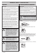
GENERAL SAFETY PRECAUTIONS Important Personal protective equipment IMPORTANT! IMPORTANT! The machine is only designed for trimming grass. A clearing saw, brushcutter or trimmer can be dangerous if used incorrectly or carelessly, and can cause serious or fatal injury to the operator or others. It is extremely important that you read and understand the contents of this operator’s manual.
GENERAL SAFETY PRECAUTIONS BOOTS Wear sturdy, non-slip boots. original positions. This movement is controlled by two independent return springs. This arrangement means that the throttle control is automatically locked at the idle setting. A B CLOTHING Wear clothes made of a strong fabric and avoid loose clothing that can catch on twigs and branches. Always wear heavy, long pants. Do not wear jewellery, shorts sandals or go barefoot. Secure hair so it is above shoulder level.
GENERAL SAFETY PRECAUTIONS Stop switch Use the stop switch to switch off the engine. Use of incorrectly wound cord or an incorrect cutting attachment increases the level of vibration. See instructions under the heading Cutting equipment. The machine′s vibration damping system reduces the transfer of vibration between the engine unit/cutting equipment and the machine′s handle unit. Start the engine and make sure the engine stops when you move the stop switch to the stop setting.
GENERAL SAFETY PRECAUTIONS Never use a machine that has a faulty muffler. • Extend the life of cutting equipment. IMPORTANT! Only use cutting attachments with the guards we recommend! See the chapter on Technical data. Refer to the instructions for the cutting attachment to check the correct way to load the cord and the correct cord diameter. Regularly check that the muffler is securely attached to the machine.
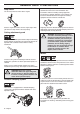
ASSEMBLY Fitting the loop handle • • Before using the unit, tighten the knob securely. Clip the loop handle onto the shaft. Note that the loop handle must be fitted between the arrows on the shaft. Dismantling: • Slide the spacer into the slot in the loop handle. Fit the nut, knob and screw. Do not overtighten. • Now adjust the trimmer to give a comfortable working position. Tighten the bolt/knob. • Loosen the coupling by turning the knob (at least 3 times). • Push and hold the button (C).
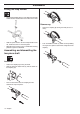
ASSEMBLY Assembling the cutting equipment • Screw on the trimmer head/plastic blades (H) in the opposite direction to the direction of rotation. H ! ! WARNING! When fitting the cutting attachment it is extremely important that the raised section on the drive disc/support flange engages correctly in the centre hole of the cutting attachment. If the cutting attachment is fitted incorrectly it can result in serious and/or fatal personal injury.
FUEL HANDLING Fuel safety Gasoline Never start the machine: 1 If you have spilled fuel on it. Wipe off the spillage and allow remaining fuel to evaporate. 2 If you have spilled fuel on yourself or your clothes, change your clothes. Wash any part of your body that has come in contact with fuel. Use soap and water. 3 If the machine is leaking fuel. Check regularly for leaks from the fuel cap and fuel lines.
FUEL HANDLING Fueling Mixing • Always mix the gasoline and oil in a clean container intended for fuel. • Always start by filling half the amount of the gasoline to be used. Then add the entire amount of oil. Mix (shake) the fuel mixture. Add the remaining amount of gasoline. • ! Mix (shake) the fuel mixture thoroughly before filling the machine’s fuel tank. WARNING! Taking the following precautions, will lessen the risk of fire: Do not smoke or place hot objects near fuel.
STARTING AND STOPPING Check before starting • • Check that the support flange is not cracked due to fatigue or due to being tightened too much. Discard the support flange if it is cracked. Starting and stopping ! WARNING! The complete clutch cover and shaft must be fitted before the machine is started, otherwise the clutch can come loose and cause personal injury. Always move the machine away from the refuelling area before starting. Place the machine on a flat surface.
STARTING AND STOPPING CAUTION! Do not pull the starter cord all the way out and do not let go of the starter handle when the cord is fully extended. This can damage the machine. CAUTION! Do not put any part of your body in marked area. Contact can result in burns to the skin, or electrical shock if the spark plug cap has been damaged. Always use gloves. Do not use a machine with damaged spark plug cap. Stopping Stop the engine by switching off the ignition.
WORKING TECHNIQUES General working instructions 6 Always hold the machine with both hands. Hold the machine on the right side of your body. 7 Keep the cutting attachment below waist level. 8 The engine must be switched off before moving. 9 Never put the machine down with the engine running unless you have it in clear sight. IMPORTANT! This section takes up the basic safety precautions for working with a trimmer.
WORKING TECHNIQUES Basic working techniques Cutting Always slow the engine to idle speed after each working operation. Long periods at full throttle without any load on the engine can lead to serious engine damage. • The trimmer is ideal for cutting grass that is difficult to reach using a normal lawn mower. Keep the cord parallel to the ground when cutting. Avoid pressing the trimmer head against the ground as this can ruin the lawn and damage the tool.
MAINTENANCE Carburetor Your Husqvarna product has been designed and manufactured to specifications that reduce harmful emissions. After the engine has used 8-10 tanks of fuel the engine will be run-in. To ensure that it continues to run at peak performance and to minimise harmful exhaust emissions after the running-in period, ask your dealer/ service workshop (who will have a rev counter at their disposal) to adjust your carburettor.
MAINTENANCE Low speed jet L High speed jet H Try to find the highest idling speed, turning the low speed needle L clockwise respectively counter-clockwise. When the highest speed has been found, turn the low speed needle L 1/4 turn counter-clockwise. The high speed jet H affects the engine power, speed, temperature and fuel consumption. If the high speed jet H is set too lean (screwed in too far) the engine speed will be too high and cause engine damage.
MAINTENANCE Muffler Cooling system CAUTION! Some mufflers are fitted with a catalytic converter. See chapter on Technical data to see whether your machine is fitted with a catalytic converter. To keep the working temperature as low as possible the machine is equipped with a cooling system. 4 The muffler is designed to reduce the noise level and to direct the exhaust gases away from the operator.
MAINTENANCE Spark plug Air filter The spark plug condition is influenced by: The air filter must be regularly cleaned to remove dust and dirt in order to avoid: • Incorrect carburetor adjustment. • An incorrect fuel mixture (too much or incorrect type of oil). • Carburettor malfunctions • Starting problems A dirty air filter. • Loss of engine power • Unnecessary wear to engine parts • Excessive fuel consumption.
MAINTENANCE Oiling the air filter Always use HUSQVARNA filter oil, art. no. 531 00 92-48. The filter oil contains a solvent to make it spread evenly through the filter. You should therefore avoid skin contact. Put the filter in a plastic bag and pour the filter oil over it. Knead the plastic bag to distribute the oil. Squeeze the excess oil out of the filter inside the plastic bag and pour off the excess before fitting the filter to the machine. Never use common engine oil.
MAINTENANCE Maintenance schedule The following is a list of the maintenance that must be performed on the machine. Most of the items are described in the Maintenance section. Maintenance Daily maintenance Clean the outside of the machine. X Make sure the throttle trigger lock and the throttle function correctly from a safety point of view. X Check that the stop switch works correctly. X Check that the cutting attachment does not rotate at idle. X Clean the air filter. Replace if necessary.
TECHNICAL DATA Technical data 327LDx Engine Cylinder displacement, cu.in/cm3 1,50/24,5 Cylinder bore, inch/mm 1,34/34 Stroke, inch/mm 1,06/27 Idle speed, rpm 2700 Recommended max. fast idle speed, rpm 11000-11700 Speed of output shaft, rpm 9300 Max. engine output, acc.
TECHNICAL DATA The accessories are recommended for use in combination with the specified power heads and have been evaluated to applicable ISO- and EN safety requirement standards by the Swedish Machinery Testing Institute. Powerhead model 327LDx Accessories Art No.
FEDERAL AND CALIFORNIA EMISSIONS CONTROL WARRANTY STATEMENT YOUR WARRANTY RIGHTS AND OBLIGATIONS The EPA (U.S. Environmental Protection Agency), CARB (California Air Resources Board), Environment Canada and Husqvarna Forest & Garden are pleased to explain the emissions control system’s warranty on your 2007 and later small off-road engine. In U.S.
FEDERAL AND CALIFORNIA EMISSIONS CONTROL WARRANTY STATEMENT EMISSION WARRANTY PARTS LIST 1 Carburetor and internal parts 2 Intake pipe, airfilter holder and carburetor bolts. 3 Airfilter and fuelfilter covered up to maintenance schedule. 4 Spark Plug, covered up to maintenance schedule 5 Ignition Module 6 Muffler with catalytic converter 7 Fuel tank WHAT IS NOT COVERED All failures caused by abuse, neglect or improper maintenance are not covered.
S35 2 3 2,4-2,7 mm .095-.
S35 3 2 2,4-2,7 mm .095-.
T35, T35x 2 3 2,4-2,7 mm .095-.
T25 2 3 2,0-2,4 mm .079-.
1151209-95 ´®z+S4•¶57¨ ´®z+S4•¶57¨ 2009-09-18