WARNING Before using our products, please read this manual carefully to understand the proper use of your unit.
English EC-declaration of conformity EC-declaration of conformity [330BT] (Applies to Europe only) Husqvarna AB, SE-561 82 Huskvarna, Sweden, tel +46-36-146500, declares under sole responsibility that the blowers Husqvarna 330BT with serial numbers dating 2007 and onwards (the year is clearly stated on the rating plate, followed by the serial number), comply with the requirements of the COUNCIL’S DIRECTIVE: of June 22, 1998 “relating to machinery” 98/37/EC, annex IIA.
English EC-declaration of conformity EC-declaration of conformity [370BTS] (Applies to Europe only) Husqvarna AB, SE-561 82 Huskvarna, Sweden, tel +46-36-146500, declares under sole responsibility that the blowers Husqvarna 370BTS with serial numbers dating 2006 and onwards (the year is clearly stated on the rating plate, followed by the serial number), comply with the requirements of the COUNCIL’S DIRECTIVE: of June 22, 1998 “relating to machinery” 98/37/EC, annex IIA.
English Contents Safety . . . . . . . . . . . . . . . . . . . . . . . . . . . . . . . . . . . . . . . . . . . . . . . . . . . . . . . . . . . . . . . . . . . 5 SAFETY FIRST . . . . . . . . . . . . . . . . . . . . . . . . . . . . . . . . . . . . . . . . . . . . . . . . . . . . . . . . 5 Notes on types of warnings . . . . . . . . . . . . . . . . . . . . . . . . . . . . . . . . . . . . . . . . . . . . . . . 5 Warning labels on the machine . . . . . . . . . . . . . . . . . . . . . . . . . . . . . . . . . . .
English Safety SAFETY FIRST Instructions contained in warnings within this manual and warning seals marked with a symbol on the blower concern critical points which must be taken into consideration to prevent possible serious bodily injury, and for this reason you are requested to read all such instructions carefully and follow them without fail.
English Symbols on the machine (a) (b) (c) (d) For safe operation and maintenance, symbols are carved in relief on the machine. Using to these indications, please be careful not to make a mistake. (a) The port to refuel the "MIX GASOLINE" Position: FUEL TANK CAP (b) The direction to close the choke Position: INTAKE CUP (c) The direction to open the choke Position: INTAKE CUP (d) The direction to stop the engine Position: THROTTLE LEVER Safety Precautions WARNING 1.
English Safety Precautions WORKING CONDITIONS 1. Refrain from operating the blower if you are tired, ill, or upset, or if you are under the influence of alcohol, drugs or medication 2. To reduce the risk of hearing loss associated with sound levels, hearing protection is required. 3. To reduce the risk of injury associated with thrown objects, always wear eye protection and foot protection. Approved protective goggles must comply with standard ANSI Z87.1 in the USA or EN 166 in EU countries. 4.
English Safety Precautions BEFORE STARTING THE ENGINE • Each time before starting the engine, inspect the entire unit to see if every part is in good order and is securely tightened in place. If any damage is found in the fuel line, the exhaust line, or the ignition wiring, do not use the blower until it has been repaired. IMPORTANT Before starting operation, always make sure to check if any obstacles are left inside the volute case and net.
English Safety Precautions MAINTENANCE TRANSPORTATION 1. In order to maintain your product in proper working order, perform the maintenance and checking operations described in the manual at regular intervals. 2. Always be sure to turn off the engine and disconnect the spark plug before performing any maintenance or checking procedures. • Drain the fuel from the fuel tank before transporting or storing the blower. • Secure the blower so that it does nor receive damage from shock doing transportation.
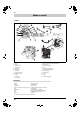
English What is what? <330BT> 1 2 3 14 6 20 8 7 23 21 13 10 4 12 11 15 18 17 19 5 16 9 22 1. Frame 13. Stop Switch with Throttle Position Setting 2. Harness 14. Engine Cover 3. Spark Plug Cap 15. Handle Bar (Option) 4. Throttle Lever 16. Fan 5. Guard Net 17. Shock Absorber (Spring) 6. Choke Lever 18. Shock Absorber (Rubber) 7. Air Cleaner 19. Band (Stopper) 8. Volute Case, Cover 20. Flexible Hose 9. “CAUTION” Label 21. Pipes 10. Elbow 22. Pad 11. Fuel Tank 23.
English What is what? <350BT> 1 3 6 2 14 18 8 10 7 21 13 19 4 12 11 17 15 5 16 9 20 1. Frame 12. Recoil Starter 2. Harness 13. Stop Switch with Throttle Position Setting 3. Spark Plug Cap 14. Engine Cover 4. Throttle Lever 15. Handle Bar (Option) 5. Net 16. Fan 6. Choke Lever 17. Shock Absorber (Rubber) 7. Air Cleaner 18. Flexible Hose 8. Volute Case, Cover 19. Pipes 9. “CAUTION” Label 20. Pad 10. Elbow 21. Flat Nozzle (Option) 11.
English What is what? <370BTS> 14 21 18 10 13 19 4 11 15 12 17 1 2 7 9 3 5 8 16 6 20 1. Frame 12. Recoil Starter 2. Harness 13. Stop Switch with Throttle Position Setting 3. Spark Plug Cap 14. Engine Cover 4. Throttle Lever 15. Handle Bar (Option) 5. Net 16. Fan 6. Choke Lever 17. Shock Absorber (Rubber) 7. Air Cleaner 18. Flexible Hose 8. Volute Case, Cover 19. Pipes 9. “CAUTION” Label 20. Pad 10. Elbow 21. Flat Nozzle (Option) 11.
English What is what? <380BTS> 2 1 21 14 18 10 19 13 4 12 11 15 7 17 3 5 16 8 9 6 20 1. Frame 12. Recoil Starter 2. Harness 13. Stop Switch with Throttle Position Setting 3. Spark Plug Cap 14. Engine Cover 4. Throttle Lever 15. Handle Bar (Option) 5. Net 16. Fan 6. Choke Lever 17. Shock Absorber (Rubber) 7. Air Cleaner 18. Flexible Hose 8. Volute Case, Cover 19. Pipes 9. “CAUTION” Label 20. Pad 10. Elbow 21. Flat Nozzle (Option) 11.
English Technical data MODEL Dimensions (L x W x H) mm (in) 330BT 350BT 370BTS 380BTS 295x387x432 (11.6x15.2x17) 351x446x479 (13.8x17.6x18) 365x464x485 (14x18x19) 410x509x497 (16.1x20x19.6) Dry Weight kg (lbs) (including pipe) 6.75 (14.9) 10.2 (22.5) 12 (26.5) 13.2 (29.1) Dry Weight kg (lbs) (without accessories) 6.1 (13.4) 9.5 (20.9) 11.2 (24.7) 12.4 (27.3) Fuel Tank Capacity liter (fl. oz) 0.9 (30.4) 1.25 (42.3) 1.75 (60.0) 2.13 (72.
English Assembly SWIVEL JOINT 1. Connect the blower and swivel joint with flexible hose. Clamp both ends of the flexible hose securely with the hardware supplied with the unit. F1 NOTE A light lubricant may be used to ease assembly of flexible hose to blower tube. THROTTLE LEVER 1. Set up the throttle holder to the swivel and tighten the screw on the holder. F2 (2) When setting up the holder, please make sure to match the holder to the convex on the swivel joint as shown in F2. 2.
English Assembly HARNESS NOTE The harness must always be worn when working with the machine. Failure to do so means you will be unable to maneuver safely and this can result in injury to yourself or others. A correctly adjusted harness and machine significantly facilitates the work. Adjust the harness to give the best working position. Tighten the side straps so that the pressure is evenly distributed across the shoulders.
English Fuel FUEL WARNING • Gasoline is very flammable. Avoid smoking or bringing any flame or sparks near fuel. Make sure to stop the engine and allow it cool before refueling the unit. Select outdoor bare ground for fueling and move at least 10ft (3m) away from the fueling point before starting the engine. • The engines are lubricated by oil specially formulated for aircooled 2-cycle gasoline engine use.
English Operation STARTING ENGINE IMPORTANT • Avoid operating the blower with the flexible tube and swivel joint disconnected. That will reduce the cooling air and the engine could be damaged by overheating. F13 (1) (4) 1. Push the primer bulb until fuel flows out in the clear tube. 2. When the engine is cool, close the choke. (3) (1) Choke Lever (2) Primer Bulb (3) OPEN (4) CLOSE [330BT] (2) F14 (1) (3) (4) (2) F15 [350BT] (1) (3) (4) (2) 3. Set the throttle lever position.
English Operation ADJUSTING IDLE SPEED [330BT] • The idling speed is set for 3000 rpm at the factory. If it is necessary to adjust the idle speed, use the adjustment screw on the top side of carburetor. F18 (1) (1) Idling Adjustment Screw [330BT][350BT] [350BT] [370BTS] [380BTS] • The idling speed is set for 2200 rpm [350BT] or 2000 rpm [370BTS/380BTS] at the factory. If it is necessary to adjust the idle speed, use the adjustment screw on the top side of carburetor.
English Maintenance Maintenance, replacement, or repair of the emission control device and systems may be performed by any non-road engine repair establishment or individual.
English Maintenance [370BTS] [380BTS] (F26) 1. Unscrew 2 knob bolts and remove the air cleaner cover. Then remove the prefilter mounted inside the air cleaner cover. (2) Prefilter (1) Knob Bolt (3) Inner Case [380BTS] (4) Paper Filter F26 (1) (2) 2. Wash the prefilter in fresh, non flammable cleaning solution (ex. warm soapy water) and then dry. (Clean the air filter once in a week.) 3. Exchange the paper filter element with new one in case it has been contaminated.
English Maintenance AIR INLET NET F31 (1) IMPORTANT • Blown air is taken in from the air inlet net. If the air flow drops during operation, stop the engine and inspect the air inlet net for blockage by obstacles. • Note that failure to remove any such obstacles may result in the engine becoming overheated and damaged. (1) Net [330BT] WARNING Never use the blower without the net on the blower. Before each use, check that the net is attached in place and is free from any damage.