Workshop manual 343R 345RX 343F 345FX 345FXT English
Workshop Manual Brushcutter, Trimmer Model 343R, 345RX, 343F, 345FX, 345FXT Contents General recommendations ___________________ 2 1. Starter __________________________________ 3 2. Electrical system _________________________ 7 3. Fuel system _____________________________ 15 4. Centrifugal clutch ________________________ 31 5. Angle gear ______________________________ 37 6. Cylinder and piston ______________________ 41 7. Crankshaft and crankcase _________________ 51 8.
General recommendations Remember: Special tools ! Never start the engine without the clutch and clutch drum mounted. ! Do not grasp hot elements such as the muffler or the clutch before they have cooled sufficiently to avoid burn injuries. Certain tasks in this handbook require the use of special tools. In sections where this is applicable, an image of the tool with an ordering number is provided. ! Avoid getting petrol on you skin or in your mouth. Use protective cream on your hands.
1 Starter 1.
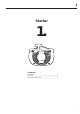
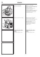
1 Starter ! WARNING! Protective glasses should be worn when working on the starter to avoid injury to the eyes if, for some reason, the return spring should fly out. Dismantling Dismantling Remove the starter from the engine. Remove the 4 bolts and lift off the starter. The cylinder cover does not need to be loosened or detached. 502 50 18-01 Loosen the spring tension. Loosen the spring tension. Pull out the starter cord about 30 cm.
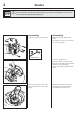
1 Starter Remove the spring cassette. ! Remove the two bolts holding the spring cassette and remove the cassette for replacement if necessary. WARNING! Wear protective glasses. The return spring can fly out and cause personal injury if improperly handled. Assembly Assembly Clean requisite parts and assemble in the reverse order as set out for dismantling. Clean all components before assembly: Change return springs, starter pulley and starter cord as needed.
1 Starter Tighten the return spring. Tighten the return spring. Check the spring tension. Lift up the starter cord when the return spring is completely loose and the cord pulled out completely. Then turn the starter pulley anticlockwise 7 revolutions. Check the spring tension. With the cord completely pulled out the cord pulley should be able to be turned at least another half revolution. Mount the starter onto the engine. Mount the starter onto the engine. Pull out the starter cord a little.
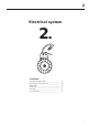
2 Electrical system 2.
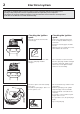
2 Electrical system The engine is equipped with an electronic ignition system completely without moving parts. Consequently, a faulty component cannot be repaired, but must be replaced by a new component. The spark in an electronic ignition system has a very short burn time and can therefore be interpreted as weak and can be difficult to see while troubleshooting. Checking the ignition spark Checking the ignition spark Clean the electrodes and check the electrode gap.
2 Electrical system If no spark occurs, disconnect the stop switch. Replace the switch if necessary If no spark occurs even now, remove the short-circuit cable from the connection point in the carburettor compartment. If the plug now sparks, the fault is either in the stop switch or the short-circuit cable. Change the switch as needed and check to see if the cable insulation is damaged. The stop switch can be easily detached with a screwdriver.
2 Electrical system Still no spark? Still no spark? Check the air gap. Check the air gap between the flywheel magnet and the ignition module. The gap should be 0.3 mm. Use a 502 51 34-02 feeler gauge. 0.3 502 51 34-02 Adjust the air gap. Adjust the air gap as needed to the correct value. • Loosen the bolts. • Position the feeler gauge and press the ignition module against the flywheel. • Tighten the bolts and check the air gap again.
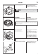
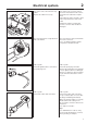
2 Electrical system Dismantling Dismantling Remove the starter, cylinder cover, and spark plug. Remove the starter, cylinder cover, and spark plug. Attach piston stop no. 502 54 15-01. Fit piston stop no. 502 54 15-01 in the spark plug hole. NOTE! 502 54 15-01 Place the piston stop so it is caught between the piston and the cylinder head. Not so it sticks out into the exhaust port. Remove the nut holding the flywheel. Remove the nut holding the flywheel. Remove the flywheel.
2 Electrical system Drive dogs Drive dogs Remove the bolts. The drive dogs can be easily replaced if they are damaged. Remove the hooks and the springs to replace them. Mind the washer (A) so as not to lose it. Remove the bolts, the hooks and the springs. Replace damaged parts. Mind the washer (A) so as not to lose it. Assemble in the reverse order. Replace damaged parts. Assemble in the reverse order. Check that the hooks can be turned freely when the bolts are tight.
2 Electrical system Separate the contacts (A-A) and (B-B). Separate the contacts (A-A) and (B-B). Then extend the cables (A) and (B) with approx. 90 cm long steel wires attached to the contacts. Then extend the cables (A) and (B) with approx. 90 cm long steel wires attached to the contacts. This is to make it easier to draw the cables to the new heating element back through the handle. 1 = black 2 = blue Remove the bolt and pull off the left grip from the handle.
2 14 Electrical system
3 Fuel system 3.
3 Fuel system In addition to the fuel tank and carburettor, the fuel system consists of the air filter, fuel filter and tank venting. All these components interact so that the engine receives the optimal mixture of fuel and air to make it as efficient as possible. Very small deviations in the carburettor setting or a blocked air filter have a large effect on the running and efficiency of the engine.
3 Fuel system Impregnate the filter with air filter oil. Impregnate the filter with air filter oil. Tip! Place the filter in a plastic bag and pour about a tablespoon of air filter oil no. 531 00 60-76 into the bag. Massage the oil into the air filter. 531 00 60-76 Tank venting Tank venting Check that the tank venting valve works correctly. Tank venting takes place through the fuel cap and needs to be functional for the engine to work. Replace the fuel cap if the valve is faulty.
3 Fuel system Clean the filter externally if it is not too dirty. If the filter is not too dirty, its surface can be cleaned with a brush. Replace the filter if required. Otherwise it must be replaced. Check the fuel hose for cracks and leaks. Make sure that the filter’s connection neck is inserted as far as possible into the fuel hose and that the O-ring is sufficiently tight so that the filter cannot slide off the tube. Fuel pump Fuel pump The fuel pump facilitates cold starts.
3 Fuel system Remove the throttle cable and fuel hose from the carburettor. Remove the carburettor. Remove the throttle cable from the carburettor’s lever arm using flat nose pliers. Pull off the fuel hose and remove the carburettor. Tip! Open the fuel cap to avoid fuel spillage caused by any excess pressure. Attach the fuel hose to the return nipple. The carburettor is made by Zama. The carburettor is made by Zama. Design, function and servicing correspond with the Walbro carburettor.
3 Fuel system The pump unit The pump unit Pumps fuel from the tank to the carburettor. This is where the pump diaphragm (E) that pumps fuel from the tank to the carburettor’s measuring unit is found. The diaphragm is affected by pressure variations in the engine’s crankcase via an impulse channel (F). If the channel is blocked, by grease or a wrongly facing gasket, for example, the pump unit does not function and the engine cannot be started.
3 Fuel system In the event of leakage – remove the needle valve. In the event of leakage – remove the needle valve. Loosen the bolt and remove the lever arm, axle, needle valve and spring. Check the needle valve and the lever arm for damage or wear. Check the needle valve for damage on the tip and in the lever arm groove. Replace damaged components with new ones. Check the lever arm for damage to the groove for the needle valve and wear on the mounting points towards the control diaphragm.
3 Fuel system Remove the movement limiters from the jet needles using flat nose pliers. Unscrew the jet needles. Do not lose the small washers (A)! Lift off the plastic and rubber guides. NOTE! Note how the jets are positioned. (For example, the H-needle is a little shorter than the L-needle). Dismantle the main jet (A) and the plug (B). Press out the main jet (A) with a suitable punch. Remove the plug (B). Carefully drill a small hole (Ø 2 mm) in the plug and pry it up with a pointed object.
3 Fuel system Assembling the carburettor Assembling the carburettor Blow the carburettor housing clean. • Blow all channels in the carburettor compartment clean • Mount a new plug. Fit a new plug. Fit a new main jet. Use a suitable punch to get a completely tight seal. • Press in a new main jet. • Mount the valves and dampers. Tip! Any numbers on the valves should be able to be read from the outside. Replace the fuel screen if it is damaged or cannot be cleaned.
3 Fuel system Attach the various parts of the measuring unit in the reverse order as set out for dismantling. Attach the various parts of the measuring unit in the reverse order as set out for dismantling. The lever arm should lie flush with the carburettor housing. Too high setting = too much fuel. Too low setting = too little fuel. NOTE! The H-needle is a little shorter than the L-needle. Check that the carburettor is sealed. No leakage is permitted at 50 kPa.
Fuel system 3 Carburettor settings ! WARNING! When testing the engine in connection with carburettor adjustment, the clutch and clutch cover must be mounted together with the shaft and angle gear under all circumstances Otherwise there is a risk of the clutch becoming loose resulting in serious personal injury. Function T The carburettor has the task of supplying a combustible fuel/air mixture to the cylinder. The amount of this mixture is controlled by the throttle.
3 Fuel system When checking the speed on a trimmer no part of the cord should be extended. NOTE! A tachometer should always be used to find the optimal setting. Use the 502 71 14-01 tachometer to check the speed. 502 71 14-01 501 60 02-03 • • Carefully screw in (clockwise) the L- and H-jets until they bottom. Now screw out (anticlockwise) the needles 1 turn. The carburettor now has the setting H = 1 and L = 1. Use special screwdriver 501 60 02-03. Start the engine and run warm for 10 minutes.
3 Fuel system Carburettor adjustment 345RX/FX Carburettor adjustment 345RX/FX Adjusting the L-needle Adjusting the H-needle 1. Mount the Trimmy Fix (4 wires) and use 3.3 mm smooth cord. The cord length should be 160 mm measured from the end of the cord to the cord bushing on the trimmer head. 2. Run the engine warm for about 5 minutes. 1. Mount the Trimmy Fix (4 wires) and use 3.3 mm smooth cord.
3 Fuel system Check for wear on pins (A) and (B). Replace the throttle control (C) and lever arm (D) if necessary. Check that the cables are properly pressed into the cut-outs (E) and that the throttle cable (F) is in the right groove. If necessary, attach it with silicon adhesive in order to facilitate assembly. Check that the protective bellows (G) are whole and that they are correctly mounted over the ball on the cable. G Remove the bolt (A) and remove the throttle from the handle.
3 Fuel system Disassemble the throttle control (A), the lock to prevent accidental throttle operation (B), the start throttle lock (C) and the throttle stop (D) in order to check if replacement is necessary. The stop switch can also be disassembled now, and replaced if necessary. Use a screwdriver to press the stop switch’s wing locks (E).
30
4 Centrifugal clutch 4.
4 Centrifugal clutch The centrifugal clutch has the task of transferring the power from the engine to the cutting equipment’s drive axle. As the name implies, it works according to a centrifugal principle. This means the clutch’s friction shoes are thrown outwards towards the clutch drum at a certain engine speed. When the friction against the drum is sufficiently great it drives the drive shaft at the same speed as the engine.
4 Centrifugal clutch Dismantle the clutch from the crankshaft. Replace the spark plug with piston stop no. 502 54 15-01. Move the engine body to the side so that the clutch becomes accessible. Unscrew the clutch from the crankshaft. 502 54 15-01 Remove the 3 bolts and separate the clutch. Fix the clutch in a vice and remove the 3 bolts. Lift off the front cover plate and the clutch shoes. NOTE! Do not lose the sleeve bearings found in the clutch shoes. Twist apart the clutch. Twist apart the clutch.
4 Centrifugal clutch Assembly Assembly Temporarily place the clutch shoes on the driving disc and loosely tighten the bolts. Temporarily place the clutch shoes on the driving disc and loosely tighten the bolts. Pry out the shoes and hook one spring to each shoe from underneath. NOTE! The bevelled edge of the shoes should be facing outwards towards the cover plate. Pry out the shoes and hook one spring to each shoe from underneath.
4 Centrifugal clutch Change the bearings in the clutch housing if necessary. Change the bearings in the clutch housing if necessary. Remove the circlip and push out the bearings with a suitable punch and hammer. Dismantling is easier if the clutch housing is heated to about 110°C. Assemble in the reverse order as set out for dismantling.
36
5 Angle gear 5.
5 Angle gear The angle gear has two purposes: The first is to gear down the engine’s high speed to better suit the lower speed a saw blade or trimmer requires to work efficiently. Second, the angle gear contributes to the saw operator’s working stance so that it is comfortable and at the same time efficient. The power from the engine, via the drive axle, shall in other words be angled so that the cutting equipment works parallel to the ground.
5 Angle gear Remove the lubricant top-up plug. Warm the gearbox and knock it against a wooden block so that the input axle falls out. Remove the lubricant top-up plug and warm the entire gearbox using a hot air gun to about 150°C. Knock the gearbox against a wooden block so that the input axle and bearing fall out. NOTE! The input axle with pinion must be dismantled first. Remove the output axle. Then remove the output axle and bearings, while the gearbox is still warm. Use puller no. 502 50 65-01.
5 Angle gear Shaft Shaft The shaft contains a drive axle guide that is easily replaced. It can be dismantled once the plastic sleeve (B) has been removed. The shaft contains a long plastic guide to prevent vibrations in the drive axle. Centre the axle control in the shaft when a new one is fitted. Bend away the plastic sleeve (B) and the O-ring (C) using a knife and pull the drive axle guide out from the shaft. Fit a new O-ring to ensure a good seal. The guide (A) is easily removed for replacement.
6 Cylinder and piston 6.
6 Cylinder and piston The cylinder and the piston are two of the components exposed to most strain in the engine. They must withstand, for example, high speeds, large temperature swings and high pressure. Moreover, they must be resistant to wear. Despite these tough working conditions, major piston and cylinder failure is relatively uncommon. The reasons for this include new coatings in the cylinder bore, new types of oil and grease and refined manufacturing techniques.
6 Cylinder and piston Dismantle the piston. Push the gudgeon pin from the piston using punch 502 52 42-01. If the pin is too tight, carefully warm the piston. 502 52 42-01 Decompression valve Decompression valve Dismantle the decompression valve. Remove the bolt (A) and the hose (B) that connect the decompression valve to the nipple on the cylinder. Unscrew the valve from the cylinder. Check that the non-return valve (A) is tight under a vacuum of – 50 kPa.
6 Cylinder and piston Inlet manifold Remove the air filter and carburettor. Remove the inlet manifold (A) from the partition (B). Check that it does not exhibit cracks or other damage that can cause leaks between the carburettor and cylinder. If necessary, fit a new inlet manifold in the reverse order as set out for dismantling. NOTE! Exercise caution if the inlet manifold is fitted using a screwdriver so as not to make any holes in the rubber wall.
6 Cylinder and piston Use a new gasket and fit the cylinder. Make sure that the inlet manifold is correctly connected to the sleeve coupling on the cylinder and that the impulse nipple sits right. Place a new cylinder pedestal gasket on the cylinder. Lubricate the piston and the inlet manifold on the cylinder with a few drops of engine oil and fit the cylinder using the smallest piston ring compressor in assembly kit 502 50 70-01.
6 Cylinder and piston The piston ring starts to stick or is completely stuck in its groove and has therefore not been able to seal against the cylinder wall, which has resulted in further, intensive temperature increases in the piston Seizure scores along the entire piston skirt on the inlet and exhaust sides. Cause: Action: • Incorrect oil mixture in the fuel. Change to a fuel with the correct oil mixture. • Too low octane fuel. Change to a higher octane petrol. • Air leaks.
6 Cylinder and piston Piston damage caused by a too high engine speed. Typical damage associated with a too high engine speed includes broken piston rings, broken circlip on the gudgeon pin, faulty bearings or that the guide pin for the piston ring has become loose. Piston ring breakage A too “lean” carburettor setting results in a too high speed and a high piston temperature.
6 Cylinder and piston Foreign objects Everything other than clean air and pure fuel that enters the engine’s inlet port causes some type of abnormal wear or damage to the cylinder and piston. This type of increased wear shows on the piston’s inlet side starting at the lower edge of the piston skirt. The damage is caused by badly filtered air that passes through the carburettor and into the engine. Small score marks and a matt, grey surface on the piston’s inlet side caused by fine dust particles.
6 Cylinder and piston Larger, harder particles that enter the engine cause serious damage to the underside of the piston skirt. Cause: Action: • Air filter damaged or missing. Fit a new air filter. • Parts from the carburettor or intake system have come loose and entered the engine. Regular service and inspection. Extensive damage to the lower part of the piston’s inlet side. Service tips Defect: Action: Broken cooling fins, damaged threads or sheared bolts by the exhaust port.
6 Cylinder and piston Wear tolerances Cylinder bore When the surface coating is worn and aluminium appears. 50 Piston ring gap Max. 1.0 mm with the piston ring inserted in the lower part of the cylinder. Piston ring groove Max. 1.6 mm. Clean the groove before checking the measurement. Piston ring play Max. 0.15 mm. Clean the groove before checking the measurement.
7 Crankshaft and crankcase 7.
7 Crankshaft and crankcase The task of the crankshaft is to transform the reciprocating motion of the piston to rotation. This requires a stable design withstanding immense pressure and rotational and bending strain, as well as high rotational speed. In addition the connecting rod is exposed to large acceleration and retardation forces as it moves between the top and bottom dead centres. This puts special demands on the bearings that must withstand quick changes in load.
Crankshaft and crankcase Separate the crankcase halves. 7 Fit tool 502 52 39-01 to the clutch side of the crankcase as illustrated. Separate the crankcase halves. 502 52 39-01 Fit tool 502 52 39-01 as illustrated. Push out the crankshaft from the crankcase half. Push out the crankshaft from the crankcase half. Remove the bearing and sealing rings from the crankcase halves. Heat the crankcase halves to approx. 150°C using a hot air gun.
7 Crankshaft and crankcase Inspecting the crankshaft Inspecting the crankshaft Inspect the large end of the connecting rod. The crankshaft cannot be reconditioned but must be replaced if it is worn or damaged. Inspect the large end of the connecting rod. If seizure marks, discolouration on the sides or damaged needle holders are found the crankshaft must be replaced. Inspect the small end of the connecting rod. Inspect the small end of the connecting rod.
Crankshaft and crankcase 7 Check that the there is no play in the fill-out plates around the crank disks (applies to models FX/FXT, RX). Check that the there is no play in the fill-out plates around the crank disks (applies to models FX/FXT, RX). Assembly Assembly Mount the bearings in the crankcase halves. Heat the crankcase halves to approx. 150°C using a hot air gun and position the bearings. Make sure they go right down into the bearing seats.
7 Crankshaft and crankcase Fit the sealing rings. Lubricate the axle spindles with engine oil and press the sealing rings until level with the crankcase using a suitable punch or tool 502 50 30-19. The metal covers of the sealing rings should face outwards! 505 38 17-09 Assemble the remaining parts in the following order: 1. Cable guide and heat guard on the carburettor side of the crankcase. 2. Protective grating on the underside of the crankcase. 3. Piston and cylinder. 4.
Crankshaft and crankcase Fit plug 503 55 22-01 instead of the decompression valve. Connect meter 531 03 06-23 and check for leakage. 7 Fit plug 503 55 22-01 instead of the decompression valve. Connect meter 531 03 06-23 to the nipple and pump up a pressure of 50 kPa (0.5 kp/cm2) in the crankcase. Max. permitted leakage: 20 kPa (0.2 kp/cm2) per 30 seconds. Connect meter 531 03 06-23 to the nipple and lower the pressure in the crankcase to 50 kPa (0.5 kp/cm2). Max. permitted leakage: 20 kPa (0.
58
Tools 8.
8 List of tools ter Star 502 50 18-01 em em al ifug r t n Ce ch clut l rica t c e El em syst t l sys Fue 502 51 91-01 531 00 60-76 531 00 48-63 502 21 58-01 502 71 13-01 502 50 83-01 531 03 03-98 502 54 15-01 t l sys e u F 0.
8 List of tools le Ang r gea r nde Cyli on pist and ft sha ase k n Cra rankc c and op ksh nt r o W e ipm equ 502 50 65-01 502 52 42-01 502 52 39-01 502 51 03-01 503 97 64-01 502 50 70-01 505 38 17-09 531 03 06-23 503 80 17-01 502 50 18-01 502 50 30-19 502 71 14-01 502 54 11-02 505 69 85-70 503 84 40-01 503 55 22-01 101 64 23-48 502 50 18-01 503 26 70-01 61
114 01 98-26 2003W24