Operator’s manual (EPA) 343F 345FX 345FXT 343FR 343FRM 343R 345RX Please read the operator’s manual carefully and make sure you understand the instructions before using the machine.
KEY TO SYMBOLS Symbols WARNING! Clearing saws, brushcutters and trimmers can be dangerous! Careless or incorrect use can result in serious or fatal injury to the operator or others. It is extremely important that you read and understand the contents of the operator’s manual. Only use non-metallic, flexible cutting attachments, i.e. trimmer heads with trimmer cord. Other symbols/decals on the machine refer to special certification requirements for certain markets.
CONTENTS Contents KEY TO SYMBOLS Symbols ................................................................ CONTENTS Contents ............................................................... Note the following before starting: ........................ INTRODUCTION Dear customer! ..................................................... WHAT IS WHAT? What is what on the clearing saw? ....................... What is what on the clearing saw? ....................... What is what on the clearing saw? .................
INTRODUCTION Dear customer! Congratulations on your choice to buy a Husqvarna product! Husqvarna is based on a tradition that dates back to 1689, when the Swedish King Karl XI ordered the construction of a factory on the banks of the Huskvarna River, for production of muskets. The location was logical, since water power was harnessed from the Huskvarna River to create the waterpowered plant.
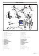
WHAT IS WHAT? 3 8 2 32 31 5 17 9 7 33 10 18 6 19 13 11 20 22 1 23 34 14 34 4 21 12 15 4 21 16 25 26 30 27 28 29 24 What is what on the clearing saw? (343R, 345RX) 1 Grass blade 18 Locking screw 2 Grease filler cap, bevel gear 19 Support cup 3 Bevel gear 20 Support flange 4 Cutting attachment guard 21 Drive disc 5 Shaft 22 Trimmer head 6 Handlebar 23 Spark plug cap and spark plug 7 Throttle control 24 Socket spanner 8 Stop switch 25 Operator’s manual 9 Thro
WHAT IS WHAT? 8 3 2 7 18 5 9 29 17 10 6 13 18 11 19 21 1 14 12 15 20 4 16 23 24 22 28 25 26 27 What is what on the clearing saw? (343F, 345FX, 345FXT) 1 Saw blade 16 Air filter cover 2 Grease filler cap, bevel gear 17 Handle adjustment 3 Bevel gear 18 Locking nut 4 Cutting attachment guard 19 Support flange 5 Shaft 20 Drive disc 6 Handlebar 21 Spark plug 7 Throttle control 22 Socket spanner 8 Stop switch 23 Operator’s manual 9 Throttle lockout 24 Transport guar
WHAT IS WHAT? 8 3 2 33 19 5 9 7 17 26 34 19 x2 21 10 6 35 13 4 20 25 18 24 14 23 12 15 22 21 19 11 4 20 16 1 21 22 1 4 20 4 20 32 26 30 27 28 29 31 What is what on the clearing saw? (343FR, 343FRM) 1 Blade 19 Locking nut 2 Grease filler cap, bevel gear 20 Drive disc 3 Bevel gear 21 Support flange 4 Cutting attachment guard 22 Metal cup 5 Shaft 23 Support cup 6 Handlebar 24 Locking screw 7 Throttle control 25 Trimmer head 8 Stop switch 26 Transport
GENERAL SAFETY PRECAUTIONS Important Personal protective equipment IMPORTANT! IMPORTANT! The machine is only designed for trimming grass, grass clearing and/or forestry clearing. A clearing saw, brushcutter or trimmer can be dangerous if used incorrectly or carelessly, and can cause serious or fatal injury to the operator or others. It is extremely important that you read and understand the contents of this operator’s manual.
GENERAL SAFETY PRECAUTIONS BOOTS Throttle lockout Wear boots with steel toe-caps and non-slip sole. The throttle lockout is designed to prevent accidental operation of the throttle control. When you press the lock (A) (i.e. when you grasp the handle) it releases the throttle control (B). When you release the handle the throttle control and the throttle lockout both move back to their original positions. This movement is controlled by two independent return springs.
GENERAL SAFETY PRECAUTIONS be checked. See instructions under the heading Maintenance. Vibration damping system Your machine is equipped with a vibration damping system that is designed to reduce vibration and make operation easier. Stop switch Use the stop switch to switch off the engine. Use of incorrectly wound cord or an incorrect cutting attachment increases the level of vibration. See instructions under the heading Cutting equipment.
GENERAL SAFETY PRECAUTIONS saw. Certain harnesses also have a quick release fitted to the support hook. If the muffler on your machine is fitted with a spark arrestor screen this must be cleaned regularly. A blocked screen will cause the engine to overheat and may lead to serious damage. Check that the harness straps are correctly positioned. Once the harness and machine have been adjusted, check that the harness quick release works correctly.
GENERAL SAFETY PRECAUTIONS should operate the socket spanner when loosening or tightening the nut. The nylon lining inside the locking nut must not be so worn that you can turn it by hand. The lining should offer a resistance of at least 1.5 Nm. The nut should be replaced after it has been put on approx. 10 times. ! ! WARNING! Always stop the engine before doing any work on the cutting attachment. This continues to rotate even after the throttle has been released.
GENERAL SAFETY PRECAUTIONS incorrectly sharpened or damaged blade increases the risk of accidents. Sharpening the saw blade • Keep the correct setting on the saw blade! Follow our instructions and use the recommended setting tool. An incorrectly set saw blade increases the risk of jamming and blade thrust, and damage to the saw blade. See the cutting attachment packaging for correct sharpening instructions.
GENERAL SAFETY PRECAUTIONS Trimmer head IMPORTANT! Always ensure the trimmer cord is wound tightly and evenly around the drum, otherwise the machine will generate harmful vibration. • Only use the recommended trimmer heads and trimmer cords. These have been tested by the manufacturer to suit a particular engine size. This is especially important when a fully automatic trimmer head is used. Only use the recommended cutting attachment. See the chapter on Technical data.
ASSEMBLY Assembling the handlebar and throttle the machine is in a comfortable working position when it hangs from the harness. CAUTION! Some models have the throttle handle fitted at the factory. • Remove the screw at the rear of the throttle handle. • Slide the throttle handle onto the right side of the handlebar, (see diagram). • Tighten the knob. Transport position, handlebar • • Align the screw hole in the throttle handle with the hole in the handlebar.
ASSEMBLY Assembling the cutting equipment ! WARNING! When fitting the cutting attachment it is extremely important that the raised section on the drive disc/support flange engages correctly in the centre hole of the cutting attachment. If the cutting attachment is fitted incorrectly it can result in serious and/or fatal personal injury. • Fit the drive disc (B) on the angle gear’s output shaft. • Centre the metal cup (P) on the drive disc’s blade guide.
ASSEMBLY Fitting the blade guard and saw blade • Place the blade (D) and support flange (F) on the output shaft. G F D CAUTION! Always use the recommended guard for the cutting attachment you are using. See chapter on Technical data. 343F, 345FX, 345FXT • B The blade guard (A) is fitted using 4 screws (L) as shown. C L • A 343FR, 343FRM, 343R, 345RX • Fit the holder (R) and bracket (J) with 2 bolts (H) on the gear housing. • Then fasten the blade guard (A) with 4 bolts (L) in the holder (N).
ASSEMBLY Fitting the trimmer guard and trimmer head Trimmy SII Fitting the shredder blade and the shredder blade guard (343FRM) • • Fit the correct trimmer guard (A) for use with the trimmer head. Hang the trimmer guard/combination guard (A) on the two hooks on the plate holder (M). Bend the guard around the shaft and tighten it with the bolt (L) on the opposite side of the shaft. Use the locking pin (C). Place the locking pin in the groove on the screw head and tighten. See diagram.
ASSEMBLY • Fit the drive disc (B) on the output shaft. Fitting other guards and cutting attachments • G F Fit the trimmer guard/combination guard (A) intended for use with the trimmer head/plastic blades. Hang the trimmer guard/combination guard (A) on the two hooks on the plate holder (M). Bend the guard around the shaft and tighten it with the bolt (L) on the opposite side of the shaft. Use the locking pin (C). Place the locking pin in the groove on the screw head and tighten. See diagram.
ASSEMBLY Adjusting the harness and clearing saw ! Adjust the height using the strap on the harness for the support hook. WARNING! When using a clearing saw it must always be hooked securely to the harness. Otherwise you will be unable to control the clearing saw safely and this can result in injury to yourself or others. Never use a harness with a defective quick release.
ASSEMBLY 2 Tighten the chest strap under your left arm so that it fits closely around your body. Correct balance 1 Forestry clearing The machine is balanced by moving the suspension ring on the machine forwards or backwards. On some models the suspension ring is fixed, however, this will then have a number of holes for the support hook. The machine is correctly balanced when it freely hangs horizontally from the support hook.
FUEL HANDLING Fuel safety Gasoline Never start the machine: 1 If you have spilled fuel on it. Wipe off the spillage and allow remaining fuel to evaporate. 2 If you have spilled fuel on yourself or your clothes, change your clothes. Wash any part of your body that has come in contact with fuel. Use soap and water. 3 If the machine is leaking fuel. Check regularly for leaks from the fuel cap and fuel lines.
FUEL HANDLING Fueling Mixing • Always mix the gasoline and oil in a clean container intended for fuel. • Always start by filling half the amount of the gasoline to be used. Then add the entire amount of oil. Mix (shake) the fuel mixture. Add the remaining amount of gasoline. • ! Mix (shake) the fuel mixture thoroughly before filling the machine’s fuel tank. WARNING! Taking the following precautions, will lessen the risk of fire: Do not smoke or place hot objects near fuel.
STARTING AND STOPPING Check before starting • Check the blade to ensure that no cracks have formed at the bottom of the teeth or by the centre hole. The most common reason why cracks are formed is that sharp corners have been formed at the bottom of the teeth while sharpening or that the blade has been used with dull teeth. Discard a blade if cracks are found.
STARTING AND STOPPING engine to idle, press the throttle lockout and throttle trigger again. CAUTION! Do not pull the starter cord all the way out and do not let go of the starter handle when the cord is fully extended. This can damage the machine. Decompression valve If the machine is fitted with a decompression valve (A): Press the valve to reduce the pressure in the cylinder and make starting easier. You should always use the decompression valve when starting the machine.
WORKING TECHNIQUES General working instructions position yourself incorrectly or make the cut in the wrong place the tree may hit you or the machine and cause you to lose control. Both situations can cause serious personal injury. IMPORTANT! This section describes the basic safety precautions for working with clearing saws and trimmers. If you encounter a situation where you are uncertain how to proceed you should ask an expert. Contact your dealer or your service workshop.
WORKING TECHNIQUES The ABC of clearing • Always use the correct equipment. • Make sure the equipment is well adjusted. • Follow the safety precautions. • Organise your work carefully. • Always use full throttle when starting to cut with the blade. • Always use sharp blades. • Avoid stones. • Control the felling direction (take advantage of the wind).
WORKING TECHNIQUES 3 o’clock and 5 o’clock so that the direction of rotation of the blade pushes the bottom of the tree to the left. conditions, so that cleared stems fall in the cleared area of the stand. • To fell a tree forwards, the bottom of the tree should be pulled backwards. Pull the blade backwards with a quick, firm movement. • Large stems must be cut from two sides. First determine which direction the stem will fall. Make the first cut on the felling side.
WORKING TECHNIQUES Brush cutting with a saw blade • Thin stems and brush are mown down. Work with a sawing movement, swinging sideways. • Try to cut several stems in a single sawing movement. • With groups of hardwood stems, first clear around the group. Start by cutting the stems high up around the outside of the group to avoid jamming. Then cut the stems to the required height. Now try to reach in with the blade and cut from the centre of the group.
WORKING TECHNIQUES Cutting • The trimmer is ideal for cutting grass that is difficult to reach using a normal lawn mower. Keep the cord parallel to the ground when cutting. Avoid pressing the trimmer head against the ground as this can ruin the lawn and damage the tool. • Do not allow the trimmer head to constantly come into contact with the ground during normal cutting. Constant contact of this type can cause damage and wear to the trimmer head.
MAINTENANCE Carburetor Your Husqvarna product has been designed and manufactured to specifications that reduce harmful emissions. After the engine has used 8-10 tanks of fuel the engine will be run-in. To ensure that it continues to run at peak performance and to minimise harmful exhaust emissions after the running-in period, ask your dealer/ service workshop (who will have a rev counter at their disposal) to adjust your carburettor.
MAINTENANCE 2 Press the start throttle lock as described under the heading Starting and stopping. 3 If the start throttle speed is too low (below 4000 rpm), turn the adjuster screw A clockwise until the cutting attachment starts to rotate. Then turn A clockwise a further 1/2 turn. 4 If the start throttle speed is too high (above 6500 rpm), turn the adjuster screw A anticlockwise until the cutting attachment stops. Then turn adjuster screw A clockwise a further 1/2 turn.
MAINTENANCE Cleaning the air filter Remove the air filter cover and take out the filter. Wash it clean in warm, soapy water. The grease in the bevel gear does not normally need to be changed except if repairs are carried out. Drive shaft An oiled foam plastic filter (available as an accessory) must be used if the machine is operated in extremely dusty conditions. See instructions under the heading Oiling the air filter. The drive shaft must be greased every three months during full-time use.
MAINTENANCE Winter use Running problems can occur when using the machine in the cold and snowy conditions caused by: • Too low engine temperature. • Icing of the air filter and carburetor. Special measures are therefore often required: • Partly mask the air inlet on the starter to increase the working temperature of the engine. • Preheat the intake air to the carburetor by using the heat from the cylinder.
MAINTENANCE Maintenance schedule The following is a list of the maintenance that must be performed on the machine. Most of the items are described in the Maintenance section. The user must only carry out the maintenance and service work described in this manual. More extensive work must be carried out by an authorised service workshop. Maintenance Clean the outside of the machine. Check that the harness is not damaged.
TECHNICAL DATA Technical data 343R 345RX 343F Engine Cylinder displacement, cu.in/cm3 2,75/45 2,75/45 2,75/45 Cylinder bore, inch/mm 1,65/42 1,65/42 1,65/42 Stroke, inch/mm 1,26/32 1,26/32 1,26/32 Idle speed, rpm 2800 2800 2800 Recommended max. speed, rpm 12500 12500 13500 Speed of output shaft, rpm 9000 9000 10500 Max. engine output, acc.
TECHNICAL DATA 345FX 345FXT Engine Cylinder displacement, cu.in/cm3 2,62/43 2,62/43 Cylinder bore, inch/mm 1,61/41 1,61/41 Stroke, inch/mm 1,26/32 1,26/32 Idle speed, rpm 2800 2800 Recommended max. speed, rpm 13500 13500 Speed of output shaft, rpm 10500 10500 Max. engine output, acc.
TECHNICAL DATA 343FR, 343FRM Engine Cylinder displacement, cu.in/cm3 2,75/45 Cylinder bore, inch/mm 1,65/42 Stroke, inch/mm 1,26/32 Idle speed, rpm 2800 Recommended max. speed, rpm 12500 Speed of output shaft, rpm 9000 Max. engine output, acc.
TECHNICAL DATA 343R, 345RX Approved accessories Type Centre hole in blades/cutters, Ø 25,4 mm Output shaft thread M12 Grass blade/grass cutter Saw blade Plastic blades Trimmer head Support cup Cutting attachment guard, Art. no.
TECHNICAL DATA 343FR Approved accessories Type Centre hole in blades/cutters, Ø 25,4 mm Output shaft thread M12 Grass blade/grass cutter Saw blade Plastic blades Trimmer head Support cup Cutting attachment guard, Art. no.
FEDERAL EMISSION CONTROL WARRANTY STATEMENT YOUR WARRANTY RIGHTS AND OBLIGATIONS The EPA (The US Environmental Protection Agency), Environment Canada and Husqvarna Forest & Garden are pleased to explain the emissions control system warranty on your 2009 and later small nonroad engine. In U.S. and Canada, new small nonroad engines must be designed, built and equipped to meet the federal stringent anti-smog standards.
FEDERAL EMISSION CONTROL WARRANTY STATEMENT MAINTENANCE, REPLACEMENT AND REPAIR OF EMISSION-RELATED PARTS Any Husqvarna Forest & Garden approved replacement part used in the performance of any warranty maintenance or repairs on emission-related parts, will be provided without charge to the owner if the part is under warranty. EMISSION CONTROL WARRANTY PARTS LIST 1 Carburetor and internal parts 2 Intake pipe, airfilter holder and carburetor bolts.
Trimmy SII 1 2,4-3,3 mm .095"-.
Auto 55 1 2 3 >1,1 Kw 1.) <1,1 Kw 2.) 2,7-3,3 mm .106-.
T45, T45x 2 3 2,7-3,3 mm .106-.
1151480-95 ´®z+SP)¶5C¨ ´®z+SP)¶5C¨ 2009-02-03