Workshop Manual 524L 525L LS LST LK RJX RJD RS RX RXT RK English
Contents Workshop Manual Contents Index ...................................................................... 4 Introduction and safety instructions ....................... 6 Technical data......................................................... 10 Engine special tools ............................................... 12 Service data........................................................... 15 Safety equipment ................................................... 18 Repair instructions.....................
Index A Air filter, dismantling and assembling.................. 32 Piston, dismantling.............................................. 45 Piston, assembling.............................................. 54 B S Bevel gear............................................................ 61 Bevel gear, dismantling....................................... 61 Bevel gear, assembling........................................ 63 Service data........................................................ 15 Special tools......
Index English - 5
Introduction and safety instructions 2 Introduction and safety instructions Contents 2.1 2.2 2.3 2.4 2.5 2.6 2.7 2.8 2.9 2.10 2.11 General ............................................................................................................................7 Safety ..............................................................................................................................7 Target group .................................................................................................
Introduction and safety instructions 2 Introduction and safety instructions 2.1 General 2.6 Structure This Workshop Manual describes in detail how to be troubleshoot, repair and test the machine. A description of different safety steps that must be taken during repair work is also given. This Workshop Manual can be used in two different ways: 2.2 Safety • Repair of a specific system on the machine. • Dismantling and assembly of the entire machine.
Introduction and safety instructions 2.8 General Instructions 2.9 Special Instructions The workshop where the machine is to be repaired must be equipped with safety equipment in accordance with local regulations. The fuel used in the machine has the following hazardous properties: • The fluid and its vapour are poisonous. • Can cause eye and skin irritation. • Can cause breathing problems. • Is highly inflammable.
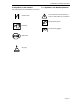
Introduction and safety instructions 2.10 Symbols on the machine 2.11 Symbols in the Workshop Manual The symbols below are embedded on the machine Choke control This symbol warns of personal injury when the instructions are not followed. Use protective gloves. Refuelling Use protective goggles.
Technical data 3 Technical data 525L: 525LS 525LST: 525RJX: 525RX: 525RXT: 525RK: 525LK 524L 525RJD 525RS Displacement cm3/cubic inch Cylinder diameter Ø mm/Ø inch Stroke length mm/inch Max. output/speed kW/rpm 25,4/ 1,55 25,4/ 1,55 25,4/ 1,55 25,4/ 1,55 25,4/ 1,55 25,4/ 1,55 25,4/ 1,55 25,4/ 1,55 25,4/ 1,55 25,4/ 1,55 25,4/ 1,55 34 / 1.34 34 / 1.34 34 / 1.34 34 / 1.34 34 / 1.34 34 / 1.34 34 / 1.34 34 / 1.34 34 / 1.34 34 / 1.34 34 / 1.
Technical data 3 Technical data 525L: 525LS: 525LST: 525RJX: 525RX: 525RXT: 525RK. 525LK 524L 525RJD 525RS Engage speed rpm Spark plug 4000 (+/- 200) 4000 (+/- 200) 4000 (+/- 200) 4000 (+/- 200) 4000 (+/- 200) 4000 (+/- 200) 4000 (+/- 200) 4000 (+/- 200) 4000 (+/- 200) 4000 (+/- 200) 4000 (+/- 200) NGK BPMR8Y NGK BPMR8Y NGK BPMR8Y NGK BPMR8Y NGK BPMR8Y NGK BPMR8Y NGK BPMR8Y NGK BPMR8Y NGK BPMR8Y NGK BPMR8Y NGK BPMR8Y Volume fuel tank Litre/US.
Engine special tools 4 Engine special tools Contents 4.1 Special tools ....................................................................................................................
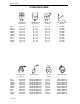
Engine special tools 4.1 Special tools Pos Description Used for Order No. 1 Torx wrench General disassembly / assembly tasks 578 28 90-01 2 Air gap tool (t 0.3mm) Adjust the air gap when installing the ignition module 514 22 10-01 3 Stopper (14 mm use) Fix piston in place when installing / 514 24 39-01 removing clutch, rotor and starter pulley.
Engine special tools For shaft (open) 7 9 8 12 11 13 14 14 - English 10
Service data 5 Service data 4,0 1,5 1,5 5,0 4,0 5,0 4,0 13 3,0 8,0 8,0 8,0 7,0 7,0 7,0 Lubricate with two-stroke oil. Note! Lubricate with Grease Some of the screws are captive screws and will remian into the cover.
Service data 18 4,0 4,0 4,0 10 7,0 1,0 7,0 6,0 16 - English
Service data 3,0 8,0 8,0 7,0 7,0 7,0 8,0 15,0 8,0 16 8,0 8,0 8,0 English - 17
safety equipment 6 Safety equipment Content 6.1 Dismantling, muffler .......................................................................................................19 6.2 Assembly, muffler ...........................................................................................................19 6.3 Dismantling, stop switch .................................................................................................19 6.4 Assembly, stop switch...........................................
Safety equipment 6.1 Dismantling the muffler Remove the cover of the muffler. Dismantle the two screws to the muffler. Also remove the gasket. 6.2 Assembling the muffler Check the muffler, and if you find any deformation or cracks replace the muffler. If the muffler is fitted with a spark arrestor mesh, put it in place first. Make sure the mesh is in the correct position, see illustration. Before assembly the muffler remove carbon gently with a screwdriver.
Safety equipment 6.5 Resistance test - stop switch Dismantle the stop switch as outlined. Clean the contact areas. test the resistance by connecting a multimeter to the stop switch. The resistance should be as follow: ”0” pressed in - less than 0.1 Ω. ”1” pressed in - more than 1000 Ω. 6.6 Dismantling Throttle B Assembly of the throttle is done in the reverse order as set out for dismantling. Position the parts in the left-hand throttle half.
Safety equipment Check that the throttle cable is fitted to the underside of the pin on the throttle trigger lock. B 6.6 Dismantling Throttle Remove screw that holding the handle bar, (A). Loosen the screws (B) holding the handle together. A Note how the recoil spring (C) and the throttle lock (D) is mounted.
Safety equipment 6.7 Assembling the throttle Put all details in the left half of the handle. Make sure that the spring is correct fitted. Make sure that all cables is fitted in the handle and will not be clamped. Assemble the throttle trigger lock (A) and the anti vibration element (B). Fit the spring (C) and the throttle lever. E A B C Fit the clamping sleeve (D). Carefully put the handle together, make sure the anti vibration element is not lost.
Safety equipment English - 23
Startapparat 7 Repair instructions Content 7.1 Dismantling, recoil pulley.................................................................................................25 7.2 7.3 7.4 7.5 7.6 7.7 7.8 7.9 7.10 7.11 7.12 7.13 7.14 7.15 7.16 7.17 7.18 7.19 7.20 7.21 7.22 7.23 7.24 7.25 7.26 7.27 7.28 Assembing, recoil pulley..................................................................................................25 Replacing starter pawls............................................................
Repair instructions 7 Repair instructions 7.1 Dismantling the recoil pulley Remove the 3 screws and lift off the starter Remove the inner cover in the starter housing. Use a flat screw driver or similar tool. WARNING! Wear protective glasses. The return spring lies tensioned in the starter and can fly out and cause personal injury with careless handling.. Offload the spring tension. Lift up the starter cord on the starter pulley and allow it to rotate clockwise. Slow the rotation with your thumb.
Repair instructions Lubricate the spindle with a little grease and fit the starter pulley. Tighten the screw. Assemble a new starter cord. Slide it into the starter pulley’s slot as illustrated and then out through the cord guide in the starter housing. Make sure the knot on the end of the cord is as small as possible! NOTE! A new starter cord can be fitted without the need of dismantling the starter! Assemble the starter handle. Tie a double knot and fold under the free end.
Repair instructions 7.3 Replacing the starter pawls A Fit the piston stop(A), no. 514 24 39-01 in the spark plug hole and loosen the starter pulley using special tool 581 96 55-01 (B). B Remove the circlip holdings the starter pawls. Lift out the starter pawls and spring for replacement. Assemble in the reverse order as set out for dismantling.
Repair instructions 7.4 Checking the ignition spark Dismantle the cylinder cover after the guard over the muffler and the air filter has been removed. Earth the spark plug on the cylinder and pull sharply on the start handle. A spark should be seen between the electrodes. If no spark is seen test with test spark plug no. 502 71 13-01. If a spark then occurs, the spark plug is faulty. Try a new spark plug. If there is still no spark, remove the short-circuit cable from the stop switch.
Repair instructions Fit the spark plug cap onto the ignition cable and make sure the ends of the wire is inserted into the centre of the spark plug cap for best contact. TIP! Lubricate the hole in the spark plug guard using for instance silicon spray to make it easier to push the ignition coil in. Still no spark? Check other cables and connections for poor contacts (dirt, corrosion, cable breakage and damaged insulation). Make sure that the cables are correctly drawn and lie in the cable grooves.
Repair instructions 7.5 Dismantling the shaft and clutch housing from engine body Remove the cylinder cover, guard over the muffler, and the air filter. Unhook the throttle cable from the carburettor and insulator. Disconnect the cables from ignition module. Remove the screws holding the clutch housing on the engine. Lift off the cover together with the shaft. 7.6 Assembling the shaft and clutch housing to the engine body Put the clutch housing on the engine. Fasten the screws to the engine body.
Repair instructions 7.7 Adjust the air gap when installing the ignition module 1 Adjust the air gap as needed to the correct value. • Loosen the bolts. • Position the gauge to adjust the gap and press the ignition module against the flywheel. • Tighten the bolts and check the air gap again. If the spark plug still does not fire, the ignition system should be replaced. A Torque: 4.0 Nm. Fig 5 C A Rotor B Gauge C Ignition module B See Fig for Ignition module model (D) and Article No (E).
Repair instructions 7.8 Fuel system In addition to the fuel tank and carburettor, the fuel system consists of the air filter, fuel filter and tank venting. All these components interact so that the engine receives the optimal mixture of fuel and air to make it as efficient as possible. Very small deviations in the carburettor setting or a blocked air filter have a large effect on the running and efficiency of the engine.
Repair instructions 7.11 Replacing the fuel filter The fuel hose in the tank contains a fuel filter. It is accessible through the fill hole. Pull out the filter with your fingers or with help of tool 502 50 83-01. If the filter is not too dirty, its surface can be cleaned with a brush. Otherwise it must be replaced. Check the fuel hose for cracks and leaks.
Repair instructions The carburettor’s design The carburettor can be divided into three different functional units: the metering unit, the blending unit, and the pump unit The metering unit The needles (A) and the fuel control functions are located here. The needle valve (B) and control diaphragm (C) are vital to the carburettor’s function. The blending unit In this section of the carburettor fuel and air are mixed in the proper proportions. The choke valve (D) and throttle valve (E) are placed here.
Repair instructions 7.14 Dismantling the carburettor Carefully remove the metering diaphragm (A) and gasket (B). Check the diaphragm for holes and wear on the pin (C). Replace the diaphragm if required. B A C Connect pressure tester 531 03 06-23 to the fuel hose nipple. Lower the carburettor in a vessel with petrol in order to discover any leaks more easily. Test the pressure at 50 kPa. No leakage is permitted. In the event of leakage – remove the needle valve.
Repair instructions Check the needle valve for damage on the tip (D) and in the lever arm groove. (E) Check the lever arm for damage to the groove (F) for the needle valve and wear on the mounting points towards the control diaphragm (G). Replace damaged components with new ones. G F E D Remove the bolt holding the cover over the pump diaphragm. Lift off the cover (H), the gasket (J) and the diaphragm (K). Check the diaphragm for damage to the valve tongues.
Repair instructions Unscrew the jet needles. Make sure they are clean and not damaged on the tip of the needle. NOTE! Note how the jets are positioned. (For example, the H-needle is a little shorter than the L-needle). Press out the main jet (A) with a suitable punch. Remove the plug (B). Carefully drill a small hole (Ø 2 mm) in the plug and pry it up with a pointed object or use special tool 531 03 01-91. Remove the valves and springs. If these components are worn, idling is disrupted.
Repair instructions 7.15 Assembling the carburettor • • Blow all channels in the carburettor compartment clean Mount a new plug (A). Use a suitable punch to get a completely tight seal. Press in a new main jet (B). • Mount the valves and springs. • Tip! Any numbers on the valves should be able to be read from the outside. Make sure valves has a perfekt seal by locking at the edge of the valve with tha carburettor backlit, a light from the choke side.
Repair instructions Attach the various parts of the measuring unit in the reverse order as set out for dismantling. The lever arm height should be 0,66 mm +-0,16 mm under carburettor housing plane. Too high setting = too much fuel. Too low setting = too little fuel. Connect pressure tester 531 03 06-23 to the fuel intake on the carburettor. Pump up the pressure to 50 kPa. Lower the carburettor in a vessel with petrol in order to discover any leaks more easily. No leakage is permitted.
Repair instructions 5. Connect the throttle cable on the carburettor with the help of flat nose pliers. Check that the cable sits correctly in the guide on the clutch housing (A) and that it sits correctly in the cut-out (B) of the insulator. 6. Connect the fuel pipe between the fuel pump and the carburettor. Assemble the remaining parts in the reverse order as set out for disman A 7.
Repair instructions Basic setting The carburettor is set to its basic setting when test run at the factory. The basic setting is “richer” than the optimal setting and should be kept during the engine’s first working hours. Thereafter the carburettor should be fine tuned.
Repair instructions 7.17 Dismantling the centrifugal clutch, flywheel and ignition module A Remove the engine cover, clutch housing and spark plug. Screw the stopper (special tool A) into the plughole to fix the piston in place.Stopper 14 mm 514 24 39-01. Remove the two screws holding the ignition module and take away the earth cable. Take out the clutch bolts and waved washers, and remove the clutch. Clutch bolt width across flats (WAF) 14mm. Waved washer thickness 0.
Repair instructions A Take out the flywheel nut (A). Rotor nut width across flats (WAF) M8 (WAF 12 mm) NOTE! Slowly turn the rotor counterclockwise, and after applying the stopper (special tool) lightly to the piston head, loosen the nut. The piston head could be damaged if force is applied too sharply when loosening the nut. Using the puller, 510 13 89-01, remove the rotor from the crankshaft. The removal bolts on the puller differ according to the engine.
Repair instructions B A 7.18 Assembling the flywheel, ignition module and centrifugal clutch 1 When setting the key on the crankshaft, make sure the end face of the key is parallel with the crankshaft. Fix the piston in place with the stopper (special tool) and tighten the rotor nut. Torque 15 Nm Fig 10 A fly wheel B Flywheel nut 2 Before installing the clutch, check the lining for wear and replace with a new product if you find any uneven wear, peeling, etc.
Repair instructions Place the ignition module in position and fit the screws. Do not tighten the screws. Make sure the gap is: 0,3 mm Tighten the bolts while pressing the ignition module the flywheel. Assembly the sparkplug, all covers and the clutch covers with shaft. 7.19 Dismantling the cylinder and piston The cylinder and the piston are two of the components exposed to most strain in the engine. They must withstand, for example, high speeds, large temperature swings and high pressure.
Repair instructions Pull the cylinder straight up without turning it. There is a risk that a piston ring may break. Remove the piston pin circlips. Use small flat nose pliers and remove the piston pin circlips. TIP! Keep your thumb over the circlip to prevent it from flying out. Press out the piston pin from the piston using the rod 513 18 12-01.
Repair instructions 7.20 Cleaning, inspection After dismantling, clean the individual components: 1. Scrape carbon deposits from the top of the piston. 2. Scrape carbon deposits from the cylinder’s combustion chamber. 3. Scrape carbon deposits from the cylinder’s exhaust port. NOTE! Scrape carefully off soot deposits using a not too sharp tool so as not to damage the soft aluminium parts. 4. 5. Wash all the components. Inspect the different components for damage and wear.
Repair instructions Insufficient lubrication The piston has small to medium size score marks usually in front of the exhaust port. In extreme cases heat development can be so great that material from the piston smears along the piston skirt and even in the cylinder bore. Generally the piston ring is undamaged and moves freely in the ring groove There can also be scores on the inlet side of the piston. Cause: Action: Incorrect carburettor setting. Recommended max. speed exceeded.
Repair instructions Piston scoring caused by heavy carbon deposits Too heavy carbon depositing can cause damage similar to that caused by insufficient lubrication. However, the piston skirt has a darker colour caused by the hot combustion gases that are blown past the piston. This type of piston damage starts at the exhaust port where carbon deposits can become loose and get trapped between the piston and the cylinder wall.
Repair instructions Piston ring guide pin vibrated loose A too high engine speed can cause the ends of the piston ring to hammer against the guide pin when the piston ring moves in its groove. The intensive hammering can drive out the pin through the top of the piston causing serious damage also to the cylinder. Damage caused by gudgeon pin circlips A too high engine speed can cause the gudgeon pin circlips to vibrate.
Repair instructions Foreign objects Everything other than clean air and pure fuel that enters the engine’s inlet port causes some type of abnormal wear or damage to the cylinder and piston. This type of increased wear shows on the piston’s inlet side starting at the lower edge of the piston skirt. The damage is caused by badly filtered air that passes through the carburettor and into the engine Inlet side.
Repair instructions Larger, harder particles that enter the engine cause serious damage to the underside of the piston skirt. Cause: Action: Air filter damaged or missing. Fit a new air filter. Parts from the carburettor or intake system have come loose and entered the engine. Regular service and inspection. Service tips Defect: Action: Broken cooling fins, damaged threads or sheared bolts by the exhaust port. In severe cases – replace the cylinder. Repair the threads using Heli-Coil.
Repair instructions Wear tolerances Cylinder bore When the surface coating is worn and aluminium appears Piston ring gap Max. 0,5 mm with the piston ring inserted in the lower part of the cylinder. Piston ring groove Max. 1,1 mm. Clean the groove before checking the measurement. Piston ring play Max. 0.1 mm. Clean the groove before checking the measurement.
Repair instructions 7.21 Assembling the piston and cylinder Clean the crankcase Fit the piston on the connecting rod so that the arrow on the piston points towards the exhaust port. Lubricate the piston pin’s needle bearing with a few drops of engine oil. NOTE! Place a rag in the crankcase opening to prevent the circlip from falling into the crankcase in case it should fly out.
Repair instructions 7.22 Dismantling crankshaft and crankcase The task of the crankshaft is to transform the reciprocating motion of the piston to rotation. This requires a stable design withstanding immense pressure and rotational and bending strain, as well as high rotational speed. In addition the connecting rod is exposed to large acceleration and retardation forces as it moves between the top and bottom dead centres. This puts special demands on the bearings that must withstand quick changes in load.
Repair instructions nspect the small end of the connecting rod. If seizure marks or discolouration are found in the bearing track the crankshaft must be replaced. Check the crank bearing. The connecting rod shall not have any radial play (up and down). It should, however, have axial play, in order to ensure good lubrication of the crank bearing among other things. Check for wear and damage on the crankshaft’s bearing and on oil seal. .
Repair instructions 7.23 Assembling the crankshaft and crankcase Check the crankshaft as set out in the section ”Inspecting the crankshaft”. Fit the new bearing in the crankcase using a press tool. During press fit of the bearing don’t push the inner bearing to fit Assemble the piston on the crankshaft. Lubricate the big-end bearing with a few drops of engine oil and position the crankshaft in the crankcase. Use new gasket. Insert the crankshaft into the crankcase bearing. Flywheel side might be tight.
Repair instructions 7.24 Replacing the clutch drum and drive shaft The centrifugal clutch has the task of transferring the power from the engine to the cutting equipment’s drive shaft. As the name implies, it works according to a centrifugal principle. This means the clutch’s friction shoes are thrown outwards towards the clutch drum at a certain engine speed. When the friction against the drum is sufficiently great it drives the drive shaft at the same speed as the engine.
Repair instructions Remove the screw (A) and screw (B) that holding the clamp connection for the shaft. B A Remove the two screws holding the clutch housing cover. Pull apart the shaft from the clutch housing.
Repair instructions Remove the upper and lower clamp. Remove the anti vibrations element Note! replace the antivibration element if it is damaged orcracked. Remove the small circlip from around the shaft on the clutch drum using suitable circlip pliers. 515 41 95-01 Dismantle the clutch drum by using a specila tool, 581 44 10-01. Dismantle the ring using a circlip pliers. Dismatle the bearing using an appropriate punch and hammer. Assemble in the reverse order as set out for dismantling.
Repair instructions 7.26 Bevel gear The angle gear has two purposes: The first is to gear down the engine’s high speed to better suit the lower speed a saw blade or trimmer requires to work efficiently. Secondly, the angle gear contributes towards the operator’s working stance so that it is comfortable and at the same time efficient. In other words, the power from the engine via the drive axle should be angled so that the cutting tool works parallel with the ground. 7.27 Dismantling the bevel gear 1.
Repair instructions Remove the screw Heat the entire angle gear using a hot air gun to approx. 110°C. Knock the gear against a wooden block so that the input axle and the bearing fall out. Now lift out the output axle. Wear protective gloves. Dismantle the bearings from the output and input axles with the help of a small bearing puller. TIP! Hold the bearing puller in a vice so that it gains a better grip around the bearing.
Repair instructions 7.28 Assembling the bevel gear D Clean all component parts and replace if damaged or worn. Fit the bearings on respective axles. This is easier if the bearings are heated to approx. 110°C using a hot air gun. The bearings on the input axle are sealed on one side. Turn the bearings so this side faces outwards. NOTE! Do not forget the circlip (A) holding the bearing on the input axle. A C B Heat the gearbox to approx.
Troubleshooting 8 Troubleshooting Contents 8.1 8.2 8.3 8.4 8.5 Engine does not start .....................................................................................................67 Engine stops working during operation ..........................................................................68 Engine is difficult to stop ................................................................................................68 Insufficient output or unstable rotation ......................................
Troubleshooting 8 Troubleshooting 8.1 Engine does not start Remove the spark plug from the cylinder, and holding the cylinder, pull the recoil starter and check whether any sparks appear between the spark plug electrodes. Symptom/Category Cause Action There are no sparks at the spark plug Spark plug Magneto Switch 1. The spark plug electrodes are wet Dry them 2. Carbon has built up on the spark plug electrodes Remove the carbon or replace with a new one. 3. Insulation is poor due to cracks, etc.
Troubleshooting 8.2 Engine stops working during operation Symptom/Category Cause Action There are no sparks at the spark plug 1. The switch has been touched, stopping the engine Restart 2. The switch is OFF Operate by setting to "RUN" or " I " 3. The plug cap has come off Fit it back on fully 4. The switch cable or high-voltage cable trunking is worn Replace 5. Internal fault in the coil Replace 6. The engine has burned out Disassemble and repair 7.
Troubleshooting 8.4 Insufficient output or unstable rotation Symptom/Category Cause Action 1. Air has entered through the fuel pipe joint, etc. Insert it securely 2. Air has entered the fuel pipe due to a crack or pin hole Replace 3. Air has entered through the insulator pulse Insert it securely pipe insertion part, etc. Compression is good and there is no flame out Excessive heat Other 4. Air has entered through the insulator and carburetor installa- tion part Replace or tighten the gasket 5.
Troubleshooting 8.5 Other Engine problems Symptom/Category Even if the engine revolution is decreased, the blade does not stop Even if the engine revolution is increased, the blade does not rotate Cause Action 1. The clutch spring is broken Replace the engine's clutch spring 2. The clutch is open due to rusting of the clutch bolts De-rust the clutch bolts, apply grease and re-assemble 3. The shoe lining has peeled off Replace the shoe 1. The shaft is broken Replace 2.
2015W11 115 75 84-26