Operator's manual HUSQVARNA AUTOMOWER® 520/550 Read the operator's manual carefully and make sure that you understand the instructions before you use the product.
Contents 1 Introduction 1.1 Support.......................................................3 1.2 Product description.....................................3 1.3 Product overview........................................4 1.4 Symbols on the product..............................5 1.5 Symbols in Automower® Connect.............. 5 1.6 Symbols on the battery...............................6 1.7 General safety instructions.........................6 1.8 Overview of the settings structure (1).........7 1.
1 Introduction Serial number: PIN code: The serial number is on the product rating plate and on the product carton. • Use the serial number to register your product on www.husqvarna.com. 1.1 Support For support about the product, speak to your Husqvarna servicing dealer. 1.2 Product description Note: Husqvarna regularly updates the appearance and function of the products. Refer to Support on page 3. The product is a robotic lawn mower.
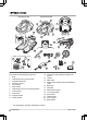
1.3 Product overview Automower® 520 Automower® 550 3 2 1 11 12 9 13 14 15 6 4 5 8 16 7 17 10 18 19 26 28 20 21 29 24 25 27 22 The numbers in the illustration represent: 1. 2. 3. 4. 5. 6. 7. 8. 9. 10. 11. Body LED indicator lamp of the product STOP/START button Ultrasonic sensors Front wheels Rear wheels LED indicator lamp of the charging station Contact strips Park button Charging station Cutting system 1 23 12. Chassis box with electronics, battery and motors 13. Handle 14.
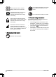
24. 25. 26. 27. Screws for securing the charging station Operator’s manual and Quick Guide Couplers for loop wire 2 Loop wire for boundary loop and guide wire 3 28. Stakes4 29. Connector for the loop wire 5 1.4 Symbols on the product These symbols can be found on the product. Study them carefully. WARNING: Read the user instructions before operating the product. WARNING: Disable the product before working on or lifting the product. WARNING: Keep a safe distance from the product when operating.
Do not discard the battery into fire and do not expose the battery to a heat source. The accessories menu is used for settings made for the accessories. The settings menu is used to set the general product settings. (Only available for Bluetooth® short-range connectivity) The security menu lets the operator select between 3 security levels. (Only available for Bluetooth® short-range connectivity) Automower® Connect is where the operator enables and disables the Automower® Connect module on the product.
1.
1.
1.
2 Safety 2.1 Safety information 2.1.1 IMPORTANT. READ CAREFULLY BEFORE USE. KEEP FOR FUTURE REFERENCE The operator is responsible for accidents or hazards occurring to other people or property.
The appliance must be disconnected from the supply mains when removing the battery. WARNING: The product can be dangerous if used incorrectly. WARNING: Do not use the product when persons, especially children, or animals, are in the work area. WARNING: Keep your hands and feet away from the rotating blades. Never put your hands or feet close to or under the product when the motor is running.
• • Use the Park function or switch off the product when persons, especially children or animals, are in the work area. Refer to To switch off the product on page 34. It is recommended to program the product for use during hours when the area is free from activity, e.g. at night. Consider that certain species, e.g. hedgehogs, are active at night. They can potentially be harmed by the product. Refer to Schedule on page 25.
2.3.3 How to lift and move the product WARNING: The product must be switched off before lifting it. The product is disabled when the Main switch is in position 0. CAUTION: Do not lift the product when it is parked in the charging station. It can damage the charging station and/or the product. Push STOP and pull the product out of the charging station before lifting it. 2.3.4 Maintenance WARNING: When the product is turned upside down the main switch must always be in the 0 position.
charging station are disconnected (power supply, boundary wire and guide wire) if there is a risk of a thunderstorm. 1. 2. 3. Mark the wires to simplify reconnecting. The charging station’s connections are marked AR, AL and G1/G2/G3. Disconnect all connected wires and the power supply. Connect all the wires and the power supply if there is no longer a risk of thunder. It is important that each wire is connected to the right place.
3 Installation 3.1 Introduction - Installation WARNING: Read and understand the safety chapter before you install the product. CAUTION: Use original spare parts and installation material. Note: Refer to www.husqvarna.com for more information about installation. 3.2 Main components for installation The installation involves the following components: • • A robotic lawn mower that mows the lawn automatically. A charging station, which has 3 functions: • • • To send control signals along the boundary wire.
max. 5 cm / 2" max. 5 cm / 2" • • • • • • Put the charging station in the lower section of the work area. Put the charging station in an area with protection from the sun. If the charging station is installed on an island, make sure to connect the guide wire to the island. Refer to To make an island on page 18. Put the power supply in an area with a roof and protection from the sun and rain. Put the power supply in an area with good airflow.
> 5 cm / 2" 35 cm /14" • Note: Make a blueprint of the work area before you install the boundary wire and guide wire. E Put the boundary wire 30 cm / 12 in. (C) from an obstacle that is 1-5 cm / 0.4-2 in. high. D F 30 cm / 12" 1-5 cm / 0.4 - 2" • C Put the boundary wire 10 cm / 4 in. (D) from an obstacle that is less than 1 cm / 0.4 in. A 10 cm / 4" B max 1 cm / 0.4" • • Put the boundary wire around all of the work area (A). Adapt the distance between the boundary wire and obstacles.
Note: If the paving stone is minimum 30 cm / 12 in. wide, use the factory setting for the Drive Past Wire function to cut all the grass adjacent to the paving stone. Refer to To set the Drive past wire on page 30. • • If you make an island, put the boundary wire that runs to and from the island near together (E). Put the wires in the same stake. Refer to To make an island on page 18. Make an eyelet (F) where the guide wire is to be connected to the boundary wire. Note: If a passage is less than 2 m / 6.
with this type of obstacle. However, obstacles that slope slightly, for example stones or large trees with raised roots, must be isolated or removed. The product can run onto this kind of obstacle causing the blades to be damaged. Use the boundary wire to isolate areas inside the work area by creating islands. When the boundary wires to and from the island are put close together, the product can run over the wire.
D A 3.4.5 Work area examples • • • • • If the charging station is put in a small area (A), make sure that the distance to the boundary wire is at a minimum 3 m / 10 ft. in front of the charging station. If the work area has a passage (B), make sure that the distance to the boundary wire is at a minimum 2 m / 6.5 ft. If the passage is smaller than 2 m / 6.5 ft., install a guide wire through the passage. Minimum passage between the boundary wire is 60 cm / 24 in.
WARNING: Do not put the power supply at a height where there is a risk it can be put in water. Do not put the power supply on the ground. WARNING: Do not encapsulate the power supply. Condensed water can harm the power supply and increase the risk of electrical shock. WARNING: Risk of Electric Shock. Install only to an residual-current device (RCD) when connecting the power supply to the wall socket. Applicable to USA/Canada. If power supply is installed outdoors: Risk of Electric Shock.
2. 3. Open the connector and put the boundary wire in the connector. 8. Cut the boundary wire with a pair of wire cutters. 9. Connect the guide wire to the boundary wire with a coupler. Close the connector with a pair of pliers. a) 4. Cut the boundary wire 1-2 cm / 0.4-0.8 in. above each connector. 5. Push the right connector onto the metal pin on the charging station with the mark "AR". 6. Push the left connector onto the metal pin on the charging station with the mark "AL". 3.5.
3.6 To put the wire into position with stakes CAUTION: Make sure that the stakes hold the boundary wire and the guide wire against the ground. Note: Make sure that you can see the ends of the boundary wire or the guide wire through the transparent area of the coupler. 6. Push the button on the coupler with an adjustable pliers. 7. Put the boundary wire or the guide wire into position with stakes. 8. Connect the charging station to the power outlet.
Note: The Bluetooth® pairing mode is active for 3 minutes. If pairing has not been successful within this time period, switch off the product. Wait until the LED status indicator is not lit, and then switch on the product again. 2. Enter the factory PIN code. 3. Log in to your Husqvarna account in the Automower® Connect app. 4. Start Bluetooth® on your mobile device. 5. Select My mowers in the Automower® Connect app, and then select the plus sign (+). 6. Select model.
with the product through Bluetooth® if you are in short-range of the product. You can use Automower® Direct without a Husqvarna account as long as you have the product PIN code. Note: The Automower® Direct connection is only valid as long as you are within Bluetooth® range. If you move out of Bluetooth® range, you will loose the Automower® Direct connection and you must do the connection process again. 3.10.6.1 To start to use Automower® Direct 1. Download the Automower® Connect app on your mobile device.
The schedule function controls which hours the product should operate and not operate. When the product is not operating it is parked in the charging station. The operating hours and days can be seen in an overview in the Automower® Connect app. The default schedule setting allows the product to operate around the clock 7 days a week. This is normally a suitable setting for a work area corresponding to the maximum capacity.
1. 2. 3. 4. Select Settings > Operation in the app. Select On/Off to enable or disable Spiral cutting. Select Settings > Spiral Cutting > Use > Intensity to select the level of the function. Select Save. 3.11.2.2 Weather timer The Weather timer automatically adjust the cutting time to the growth of the grass. The product is not permitted to operate more than the schedule settings. Note: When using Weather timer, it is recommended to make as much operating time as possible available for the Weather timer.
when the charging station is put near an obstacle such as a bush or wall and the signal reaches to the other side of the obstacle. The product knows that it is close to the charging station and tries to dock, but the objects prevents it. The options are min, avg (average) or max. Note: It is usually better to move the charging station, than to decrease the range of the charging station signal. 1. Select Settings > Installation > Find charging station in the app. 2. Select signal range. 3. Select Save.
4. Select Test: Area 1-5 setup. 5. Follow the instructions in the app to start the test. 6. Push the STOP button when the product is at the distance you select to measure. The distance shows in the app. To do a test of the Lawn Coverage function 1. Put the product in the charging station. 2. Select Settings > Installation > Lawn coverage in the app. Select Test: Area 1-5 setup. Follow the instructions in the app to start the test. The product will run to the starting point for this area. 3. 4. 5.
To set the Drive past wire 1. 2. 3. Select Settings > Installation > Drive past wire in the app. Move the horizontal bar to set the distance. Select Save. 3.11.4 Accessories Settings for accessories mounted on the product can be made in this menu. 3.11.4.1 To avoid collisions with the mower house When this option is enabled, the wear on the product and the house is reduced, but it can result in more uncut grass around the charging station. 1. Select Settings > Installation > Mower house in the app. 2.
4. Enter the new PIN code to confirm. 5. Make a note of the new PIN code in Memo. Refer to Introduction on page 3. 3.11.6.3 Theft protection to deactivate the alarm and to start the product again. To set the center position for the GeoFence function In the Theft protection menu it is possible to set the alarm duration and also what events should trigger the alarm. The factory setting is to require PIN code and the alarm duration is 1 min. 1. Select Settings > Security > GeoFence in the app. 2.
3.11.9.1 To connect to the product with Husqvarna Fleet Services™ 1. Download the Husqvarna Fleet Services™ app and Automower® Connect app to your mobile device. 2. Create a Husqvarna Fleet Services™ account (www.husqvarna.com). 3. Log on to the Husqvarna Fleet Services™ app. 4. Set the Main switch on the product to position 1. Note: The Bluetooth® pairing mode is active for 3 minutes. If pairing has not been successful within this time period, switch off the product.
4 Operation 4.1 Main switch WARNING: Read the safety instructions carefully before you start the product. WARNING: Keep your hands and feet away from the rotating blades. Never put your hands or feet close to or under the product when the motor is running. WARNING: Do not use the product when persons, especially children, or animals, are in the work area. 4.3 Operating mode - Start When Start has been selected the following operation selections can be selected.
between the main area and the secondary area. The product mows for a selected period of time or until the battery is empty. When the battery is empty, the product stops and the message Needs manual charging shows in the product display. Put the product in the charging station to charge the battery. When the battery is charged, the product moves out of the charging station and stops. The product is now prepared to start operation, but needs confirmation from the operator first.
2. Set the Main switch to position 0. and the charging station is connected. Refer to contact and charging strips in Product overview on page 4. 3. Make sure that the charging is in progress in the Automower® Connect app. WARNING: Always switch off the product using the main switch if it requires maintenance, or if the product must be moved outside the work area. 4.7 To adjust the cutting height with Automower® Connect The cutting height can be varied from MIN (2 cm / 0.8 in.) to MAX (6 cm / 2.5 in.).
5 Maintenance 5.1 Introduction - maintenance WARNING: The product must be switched off before any maintenance is done. The product is disabled when the LED status indicator is not lit. accessory. Contact your Husqvarna representative for more information. CAUTION: Never use a high-pressure washer to clean the product. Never use solvents for cleaning. 5.2.1 Chassis and blade disc WARNING: Wear protective gloves.
Clean the charging station regularly from grass, leaves, twigs and other objects that may impede docking. 5.3 Replace the blades WARNING: Use blades and screws of the right type. Husqvarna can only guarantee safety when using original blades. Only replacing the blades and reusing the screw can result in a screw wearing during mowing. The blades can then be propelled from under the body and cause serious injury. Replace worn or damaged parts for safety reasons.
5.5 Winter service Take your product to your Husqvarna central service for service prior to winter storage. Regular winter service will maintain the product in good condition and create the best conditions for a new season without any disruptions. Service usually includes the following: • • • • • Thorough cleaning of the body, the chassis, the blade disc and all other moving parts. Testing of the product’s function and components. Checking and, if required, replacing wear items such as blades and bearings.
6 Troubleshooting 6.1 Introduction - troubleshooting All messages can be found in the Messages menu in Automower® Connect. More suggestions for steps to take in the event of malfunction or symptoms can be found on www.husqvarna.com. Note: The Messages menu is only available for short-range connectivity (Bluetooth®). 6.2 Fault messages The list below shows a number of fault messages that may be shown in the display of the product.
Message Cause Action No loop signal The power supply or the low-voltage cable is not connected. Examine the LED status on the charging station. If there is no power to the charging station, the LED is not lit. Examine the wall socket connection and if a residual-current device is engaged. Make sure that the low-voltage cable is connected to the charging station. The power supply or the low-voltage cable is damaged. Replace the power supply or low-voltage cable.
Message Cause Outside work area The boundary wire connections to the charging station are crossed. The boundary wire is too close to the edge of the work area. The work area slopes too much by the boundary loop. Action Make sure that the boundary wire is connected correctly to the charging station. Refer to To install the boundary wire on page 21. Make sure that the boundary wire is put down correctly. Refer to To examine where to put the boundary wire on page 16.
Message Cause Action Wheel motor over- Grass or other objects is wound around Examine the drive wheel and remove loaded the drive wheel. grass or other objects. Charging station blocked Stuck in charging station The contact between the charging strips and contact strips may be poor and the product has made a number of attempts to charge. Put the product in the charging station and check that the charging plates and contact plates make good contact. An object is obstructing the product.
Message Cause Action Alarm! Mower switched off The alarm was activated because the product was switched OFF. Alarm! Mower stopped The alarm was activated because the product was stopped. Adjust the mower security settings in the Security menu. Refer to Security (Bluetooth® only) on page 30. Alarm! Mower lifted The alarm was activated because the product was lifted. Alarm! Mower tilted The alarm was activated because the product was tilted. The product is tilted more than the maximum angle.
Message Cause Battery temperature outside limits The product does not operate if the bat- The product starts to operate again tery temperature is too high or too low. when the temperature is between the set limits and the schedule settings let the product to operate. Make sure that the charging station is put in an area with protection from the sun. Charging current too high Wrong or faulty power supply unit. Connectivity problem Potential problem on the connectivity circuit board in the product.
6.3 Information messages The list below shows a number of information messages that may be found in the Messages menu in the Automower® Connect app. Contact your local Husqvarna representative if the same message appears often. Message Cause Action Low battery The product cannot find the charging station. Change the position of the guide wire. Refer to To examine where to put the guide wire on page 19. Make sure that the installation settings about how to find the charging station is correct.
Message Cause Action Guide 1 not found The guide wire is not connected to the charging station. Check that the guide wire’s connector is tightly connected to the charging station. Refer to To install the guide wire on page 22. Break in the guide wire. Find out where the break is. Replace the damaged section of the guide wire with a new loop wire and splice using an original coupler. The guide wire is not connected to the boundary loop.
Message Cause Action Connection settings restored Settings for wireless connectivity have been restored due to an error. Check and revise settings if necessary. SIM card requires PIN The SIM card must be unlocked. Make sure the correct SIM PIN has been entered into the mower's menu (Network > SIM card). Contact your local Husqvarna representative if this message appears often. SIM card locked The SIM card must be replaced. Contact your local Husqvarna representative.
6.5 LED indicator lamp on the product There is a LED indicator lamp on top of the product, which shows the current status: Light Cause Action Green solid light The product is either mowing the lawn, or leaving the charging station. No action required. Blue solid light The product is either paused, parked, charging or is searching for the charging station. No action required. Yellow solid light The STOP button has been pressed. Press the START button on top of the product to start it again.
6.6 Symptoms If your product does not work as expected, follow the symptoms guide below. There is a FAQ (Frequently Asked Questions) on www.husqvarna.com which provides more detailed answers to a number of standard questions. Contact your local Husqvarna representative if you still cannot find the reason for the fault. Symptoms Cause Action The product has difficulty docking. The boundary wire is not laid in a long straight line that is far enough out from the charging station.
Symptoms Cause Action The product is The product is parked due to a schedparked for hours in ule setting, or because Park until furthe charging stather notice has been chosen in the app. tion. The product does not operate if the battery temperature is too high or too low. Open the app and edit the schedule settings, or go to Dashboard and start the product. The product often Spiral cutting is a natural part of the moves in circles or product's movement patter. spirals.
Symptoms Cause Action Uneven mowing results. The product works too few hours per day. Increase the mowing time. Refer to Schedule on page 25. The Weather timer senses that the lawn has been mowed more than it actually has. Increase the intensity level in the Weather timer. Disable the Weather timer if this does not help. The How often? setting is incorrect in relation to the layout of the work area. Note: Not applicable if GPS assisted navigation is enabled.
have occurred until there is only a very short section of the wire left. boundary wire (thick black line in the illustration). The following method does not work if ECO mode is activated. Make sure first that ECO mode is turned off. Refer to ECO mode on page 27. 1. Check that the indicator lamp in the charging station flashes blue, which indicates a break in the boundary loop. Refer to LED indicator lamp on the charging station on page 47. AL G1 Guide 2.
AR 4. 5. Continue until only a very short section of the wire remains which is the difference between a solid green light and a flashing blue light. Then follow instruction in step 5 below. If indicator lamp still flashes blue in step 3 above: Put AL and G1 back in their original positions. Then switch AR and G1. If indicator lamp now is lit with a solid green light then disconnect AL and connect a new boundary wire to AL.
7 Transportation, storage and disposal 7.1 Transportation The supplied Li-ion batteries obey the Dangerous Goods Legislation requirements. • • Obey all applicable national regulations. Obey the special requirement on package and labels for commercial transportations, including by third parties and forwarding agents. 1. Disconnect the product with the Main switch. Refer to To switch off the product on page 34. 2.
8 Technical data 8.1 Technical data Dimensions Automower® 520 Automower® 550 Length, cm / in. 72 / 28.3 72 / 28.3 Width, cm / in. 56 / 22 56 / 22 Height, cm / in. 31 / 12 31 / 12 Weight, kg / lbs 13.3 / 29.3 13.5 / 29.8 Electrical system Automower® 520 Automower® 550 Battery, Lithium-Ion 18V, 4.0 Ah, Art. No 593 11 41-02, 593 11 42-01 Battery, Lithium-Ion 18.25V, 4.0 Ah, Art. No 593 11 41-03, 593 11 42-02 Battery, Lithium-Ion 18V, 5.0 Ah, Art. No 593 11 84-01, 593 11 85-01 (2 pcs.) 5.
Noise emissions measured in the environment as sound power7 Automower® 520 Automower® 550 Measured sound power noise level, dB (A) 58 60 Guaranteed sound power noise level, dB (A) 59 61 Sound pressure noise level at the operator’s ear, dB (A) 8 47 49 Mowing Automower® 520 Automower® 550 Cutting system 3 pivoted cutting blades Maximum blade motor speed, rpm 2300 2300 Power consumption during cutting, W +/- 20 % 30 35 Cutting height, cm / in. 2-6 / 0.8-2.4 2-6 / 0.8-2.
Frequency Band Support Bluetooth® Frequency range 2400.0-2483.
9 Warranty 9.1 Warranty terms Husqvarna® warranty covers this product's functionality for a period of 2 years from date of purchase. The warranty covers serious faults relating to materials or manufacturing faults. Within the warranty period, we will replace the product or repair it at no charge if the following terms are met: • • The product and the charging station may only be used in compliance with the instructions in this Operator’s Manual.
10 EC Declaration of Conformity 10.1 EC Declaration of Conformity Husqvarna AB, SE-561 82 Huskvarna, Sweden, tel: +46-36-146500, declares that the robotic lawn mowers Automower® 520 and Automower® 550 with serial numbers dating 2020 week 3 and onwards (the year and week is clearly stated on the rating plate, followed by the serial number), comply with the requirements of the COUNCIL’S DIRECTIVE: • Directive “relating to machinery” 2006/42/EC.
AUTOMOWER® is a trademark owned by Husqvarna AB. Copyright © 2020 HUSQVARNA. All rights reserved. www.husqvarna.