
Operators Manual


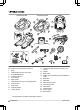


Table Of Contents
- Contents
- Introduction
- Safety
- Installation
- Introduction - Installation
- Main components for installation
- General preparations
- Before the installation of the wires
- Installation of the product
- To put the wire into position with stakes
- To bury the boundary wire or the guide wire
- To extend the boundary wire or the guide wire
- After the installation of the product
- Automower® Connect
- Settings in Automower® Connect
- Operation
- Maintenance
- Troubleshooting
- Transportation, storage and disposal
- Technical data
- Warranty
- EC Declaration of Conformity

1.3 Product overview
Automower® 520 Automower® 550
1
4
6
14
10
7
13
17
16
8
5
11
12
2
3
9
25
28
26
29
27
22
18
20
21
19
24
23
15
The numbers in the illustration represent:
1. Body
2. LED indicator lamp of the product
3. STOP/START button
4. Ultrasonic sensors
5. Front wheels
6. Rear wheels
7. LED indicator lamp of the charging station
8. Contact strips
9. Park button
10. Charging station
11. Cutting system
12. Chassis box with electronics, battery and
motors
13. Handle
14. Main switch
15. Rating plate (including product identification
code)
16. Blade disc
17. Skid plate
18. Measurement gauge
19. Low voltage cable
20. Alarm decal
21. Cable markers
22. Power supply
1
23. Extra blades
1
The appearance may differ depending on market
4 - Introduction 1439 - 002 -