
Product Manual


TOOLS REQUIRED
• Wrench ½" (2)
• Wrench
9
/16" (2)
• Wrench
7
/16" (2)
• Ft/Lbs Torque Wrench
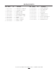
PARTS IDENTIFICATION
• Drill
• Drill Bit
5
/16"
• Socket and Ratchet
9
/16"
• Standard Screwdriver
NOTE: When the terms RH (right hand) or LH (left hand) are
used, it refers to when the operator is seated on the mower.
CONTAINER CONTENTS
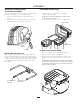
• Bagger Assembly • Cover Assembly
• Upper Chute • Lower Chute
• Mounting Brackets • Bag of Hardware
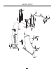
COVER ASSEMBLY
BAG
CONTAINERS
LOWER CHUTE
UPPER CHUTE
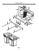
INSTALL PLATE AND HANGER
1. Using hardware provided in kit, attach support mount to
unit.
2. Attach hanger bracket to support mount. Do not fully
tighten nuts at this time.
Support Mount
Hanger Bracket
3. Secure the rear end of the support straps to the outside
of the hanger assembly. Set the reinforcement plates to
the outside of the tank brackets and fasten the front end
of support strap to the tank bracket and the reinforcment
plate with round head bolt. Attach the front end of
reinforcement plate to the tank bracket with a hex bolt.
Fully secure all mounting hardware. See illustration.
NOTE: Depending on model, rear guard hole may need to
be drilled out to
5
/16" if kit hardware is too large.
Support Straps
Reinforcement
Plate
Hex Bolt Placement
Round Head
Bolt Placement
BAG FULL
INDICATOR
5
ASSEMBLY