
Product Manual


8
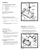
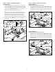
STEP 7: INSTALL EXTENSION SPRING
(SEE FIGURE 6)
• Lightly apply grease to the end of the arm on the tilt
anchor assembly and install the tilt bracket assembly
to the arm using a 1/2" x 1" hex bolt (C) and 1/2" hex
lock nut (N). Tighten then loosen the nut 1/4 turn, or
until the tilt bracket assembly pivots freely.
• Install a 1/4" x 1-3/4" hex bolt (I) through the end of
the extension spring on the tilt bracket assembly and
then install a 1/4" hex nut (V) onto the bolt. Next,
insert the end of the bolt into the hole in the arm of
the tilt anchor assembly and install a 1/4" nylock nut
(U) onto the bolt. Tighten the nuts to secure the bolt
to the arm.
FIGURE 6
1/4" NYLOCK NUT (U)
1/4" HEX NUT (V)
1/4" x 1-3/4"
HEX BOLT (I)
1/2" x 1" HEX BOLT (C)
1/2" HEX LOCK
NUT (N)
ARM
EXTENSION SPRING
5/16" HEX NUTS (T)
5/8" SPACERS (X)
5/16" x 3-1/2"
HEX BOLT (H)
STOP
BRACKET
LONG COMPRESSION
SPRING (NN)
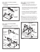
FIGURE 7A
FIGURE 7B
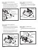
STEP 8: INSTALL STOP BRACKET BOLT
(SEE FIGURE 7A)
For lift straps installed in front holes
• Install the long compression spring (NN) and then the
two 5/8" spacers (X) onto the 5/16" x 3-1/2" hex bolt (H).
Insert the bolt into the stop bracket and install two 5/16"
hex nuts (T) onto the bolt. Adjust nuts later in step 29.
5/16" HEX NUTS (T)
5/8" SPACERS (X)
5/16" x 3-1/2"
HEX BOLT (H)
STOP
BRACKET
LONG COMPRESSION
SPRING (NN)
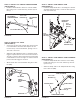
(SEE FIGURE 7B)
For lift straps installed in rear holes
• Install the long compression spring (NN) and then a 5/8"
spacer (X) onto the 5/16" x 3-1/2" hex bolt (H). Insert
the bolt into the stop bracket and install a 5/8" spacer
(X) and two 5/16" hex nuts (T) onto the bolt. Adjust nuts
later in step 29.