
Product Manual


9
5/16" x 1-3/4"
HEX BO L T (G)
5/16" NYLOCK
NUTS (S)
LIFT HANDLE
TUBE
INDEX
BR A CKE T
FIGURE 11
STEP 12: INSTALL LIFT HANDLE TUBE
(SEE FIGURE 11)
• Install the lift handle tube into the index bracket using
two 5/16" x 1-3/4" hex bolts (G) and 5/16" nylock nuts
(S).
TILT STOP
BRACKET (PP)
3/8" NYLOCK
NUT (R)
3/8" WASHER (FF)
3/8" x 1"
CARRIAGE BOLT (J)
FIGURE 10
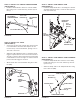
STEP 11: INSTALL TILT STOP BRACKETS
(SEE FIGURE 10)
• Install a tilt stop bracket (PP) to each side of the
bucket using a 3/8" x 1" carriage bolt (J), a small 3/8"
washer (FF) and 3/8" nylock nut (R). Do not tighten
the nuts until step 28.
5/8" W ASHERS (II)
5/8" WASHERS (II)
1/8" x 1-1/4"
COTTER PIN (BB)
1/8" x 1-1/4"
C O TTER PI N (BB)
DUMP
CONT R O L
R O D
1/8" x 1-1/4"
C O TTE R
PINS (BB)
FIGURE 9
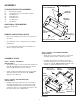
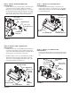
STEP 10: INSTALL DUMP CONTROL ROD
(SEE FIGURE 9)
• Install a 1/8" x 1-1/4" cotter pin (BB) into the inside hole
in each end of the dump control rod. Spread the ends
of the cotter pins and wrap around the rod. Install a 5/8"
washer (II) onto each end of the control rod.
• Install the dump control rod to the dump pivot bracket
and bucket. Fasten using two 5/8" washers (II) and
1/8" x 1-1/4" cotter pins (BB). Spread the ends of the
cotter pins and wrap around the rod.
1" WASHERS (KK)
1/8" x 1-1/2"
COTTER PIN (CC)
APPLY
GREASE
DUMP PIVOT
BRACKET
1/8" x 1-1/2"
COTTER PIN (CC)
FIGURE 8
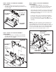
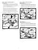
STEP 9: INSTALL DUMP PIVOT BRACKET
(SEE FIGURE 8)
• Install a 1/8" x 1-1/2" cotter pin (CC) to the inside hole
in the shaft shown in gure 8, and then install a 1"
washer (LL) onto the shaft. Apply grease to the end of
the shaft and install the dump pivot bracket assembly
onto the shaft. Install a 1" washer (KK) onto the shaft
and secure it using a 1/8" x 1-1/2" cotter pin (CC).