650RTT Owner's Manual
SAFETY RULES Safe Operation Practices for Walk-Behind Powered Rotary Tillers TRAINING • • • • • Read the Owner’s Manual carefully. Be thoroughly familiar with the controls and the proper use of the equipment. Know how to stop the unit and disengage the controls quickly. Never allow children to operate the equipment. Never allow adults to operate the equipment without proper instruction. Keep the area of operation clear of all persons, particularly small children, and pets.
CUSTOMER RESPONSIBILITIES PRODUCT SPECIFICATIONS Gasoline Capacity: 3 Quarts Unleaded Regular OIL (API-SF/SJ): (Capacity 20 oz./0.6L) SAE 30 (Above 40°F) SAE 5W-30/10W30 (Below 40°F) Spark Plug: (Gap: .030"/0.76mm) Champion RC12YC • • • Read and observe the safety rules. Follow a regular schedule in maintaining, caring for and using your tiller. Follow instructions under “Maintenance” and “Storage” sections of this Owner’s Manual.
ASSEMBLY Your new tiller has been assembled at the factory with exception of those parts left unassembled for shipping purposes. To ensure safe and proper operation of your tiller all parts and hardware you assemble must be tightened securely. Use the correct tools as necessary to insure proper tightness. TOOLS REQUIRED FOR ASSEMBLY FRONT A socket wrench set will make assembly easier. Standard wrench sizes are listed.
ASSEMBLY UNPACKING CARTON (See Fig. 2) • CAUTION: Be careful of exposed staples when handling or disposing of cartoning material. Grasp handle assembly. Hold in “up” position. Be sure handle lock remains in gearcase notch. Slide handle assembly into position. HANDLE ASSEMBLY "UP" POSITION IMPORTANT: WHEN UNPACKING AND ASSEMBLING TILLER, BE CAREFUL NOT TO STRETCH OR KINK CABLES.
ASSEMBLY ATTACH CLUTCH CABLE (See Fig. 6) CONNECT SHIFT ROD (See Fig. 7) • • • Hook end of clutch cable through hole in control bar bracket. CONTROL BAR BRACKET Insert end of shift rod into hole of shift lever indicator. Insert hairpin clip through hole of shift rod to secure. SHIFT ROD SHIFT LEVER INDICATOR HAIRPIN CLIP CONTROL BAR CLUTCH CABLE CONTROL BAR BRACKET FIG. 7 REMOVE TILLER FROM CRATE • END OF CLUTCH CABLE • FIG. 6 • Make sure shift lever indicator is in “N” position (See Fig.
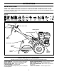
OPERATION KNOW YOUR TILLER READ THIS OWNER'S MANUAL AND SAFETY RULES BEFORE OPERATING YOUR TILLER. Compare the illustrations with your tiller to familiarize yourself with the location of various controls and adjustments. Save this manual for future reference. These symbols may appear on your Tiller or in literature supplied with the product. Learn and understand their meaning.
OPERATION 00155 The operation of any tiller can result in foreign objects thrown into the eyes, which can result in severe eye damage. Always wear safety glasses or eye shields before starting your tiller and while tilling. We recommend a wide vision safety mask for over spectacles or standard safety glasses. HOW TO USE YOUR TILLER Know how to operate all controls before adding fuel and oil or attempting to start engine. SHALLOWEST TILLING (CULTIVATING) STOPPING (See Fig.
OPERATION • When you have completed your turn-around, release the drive control bar and lower handle. Place shift lever in till position and move throttle control to desired speed. To begin tilling, hold drive control bar against the handle. OIL LEVEL OUTER SIDE SHIELDS (See Fig. 11) The back edges of the outer side shields are slotted so that the shields can be raised for deep tilling and lowered for shallow tilling to protect small plants from being buried. Loosen nut “A” in slot and nut “B”.
OPERATION • • • Turn fuel shut-off valve 1/4 turn to open position. Move choke control to choke position. Grasp recoil starter handle with one hand and grasp tiller handle with other hand. Pull rope out slowly until engine reaches start of compression cycle (rope will pull slightly harder at this point). • Pull recoil starter handle quickly. Do not let starter handle snap back against starter. • If engine fires but does not start, move choke control to half choke position.
MAINTENANCE YS EA SO OU N RS RS ER SERVICE DATES EV Y5 ER EV EV ER Y2 0H 5H OU UR HO CH Y5 EA ER RE EV FO BE FILL IN DATES AS YOU COMPLETE REGULAR SERVICE S US E MAINTENANCE SCHEDULE Check Engine Oil Level Change Engine Oil 1,2 Oil Pivot Points Inspect Spark Arrester / Muffler Inspect Air Screen Clean or Replace Air Cleaner Cartridge 2 Clean Engine Cylinder Fins Replace Spark Plug RH Gear Case Grease Fitting (1oz.
MAINTENANCE Disconnect spark plug wire before performing any maintenance (except carburetor adjustment) to prevent accidental starting of engine. Prevent fires! Keep the engine free of grass, leaves, spilled oil, or fuel. Remove fuel from tank before tipping unit for maintenance. Clean muffler area of all grass, dirt, and debris. Do not touch hot muffler or cylinder fins as contact may cause burns. ENGINE LUBRICATION Use only high quality detergent oil rated with API service classification SF-SJ.
MAINTENANCE MUFFLER COVER KNOB Do not operate tiller without muffler. Do not tamper with exhaust system. Damaged mufflers or spark arresters could create a fire hazard. Inspect periodically and replace if necessary. If your engine is equipped with a spark arrester screen assembly, remove every 50 hours for cleaning and inspection. Replace if damaged.
SERVICE AND ADJUSTMENTS CAUTION: Disconnect spark plug wire from spark plug and place wire where it cannot come into contact with plug. TILLER CLEVIS PIN TO ADJUST HANDLE HEIGHT (See Fig. 20) Select handle height best suited for your tilling conditions. Handle height will be different when tiller digs into soil. • First loosen handle lock lever. • Handle can be positioned at different settings between “HIGH” and “LOW” positions. • Retighten handle lock lever securely after adjusting.
SERVICE AND ADJUSTMENTS TO REPLACE GROUND DRIVE BELT (See Fig. 23) GROUND DRIVE BELT ADJUSTMENT (See Fig. 23) • For proper belt tension, the extension spring should have about 5/8 inch stretch when drive control bar is in “ENGAGED” position. This tension can be attained as follows: • Loosen cable clip screw securing the drive control cable. • Slide cable forward for less tension and rearward for more tension until about 5/8 inch stretch is obtained while the drive control bar is engaged.
SERVICE AND ADJUSTMENTS • TINE REPLACEMENT (See Figs. 24, 25, and 26) CAUTION: Tines are sharp. Wear gloves or other protection when handling tines. • A badly worn tine causes your tiller to work harder and dig more shallow. Most important, worn tines cannot chop and shred organic matter as effectively nor bury it as deeply as good tines. A tine this worn needs to be replaced.
SERVICE AND ADJUSTMENTS ENGINE TO ADJUST CARBURETOR The carburetor has been preset at the factory and adjustment should not be necessary. However, engine performance can be affected by differences in fuel, temperature, altitude or load. If the carburetor does need adjustment, contact your nearest authorized service center/department TO ADJUST THROTTLE CONTROL CABLE (See Fig. 27) The throttle control has been preset at the factory and adjustment should not be necessary.
STORAGE Immediately prepare your tiller for storage at the end of the season or if the unit will not be used for 30 days or more. ENGINE OIL Drain oil (with engine warm) and replace with clean oil. (See “ENGINE” in the Maintenance section of this manual). WARNING: Never store the tiller with gasoline in the tank inside a building where fumes may reach an open flame or spark. Allow the engine to cool before storing in any enclosure.
TROUBLESHOOTING POINTS PROBLEM Will not start CAUSE CORRECTION 1. 2. 3. 4. 5. Out of fuel. Engine not “CHOKED” properly. Engine flooded. Dirty air cleaner. Water in fuel. 1. 2. 3. 4. 5. 6. 7. 8. 9. 10. Clogged fuel tank. Loose spark plug wire. Bad spark plug or improper gap. Carburetor out of adjustment. Oil soaked air filter. 6. 7. 8. 9. 10. Fill fuel tank. See “TO START ENGINE” in Operation section. Wait several minutes before attempting to start. Clean or replace air cleaner cartridge.
REPAIR PARTS TILLER - - MODEL NUMBER 650RTT (650BRTTA), PRODUCT NUMBER 954 32 93-25 HANDLE ASSEMBLY 8 9 7 6 4 3 5 26 12 3 14 2 2 10 13 11 27 1 25 15 26 24 23 22 30 21 16 19 18 20 31 17 11 handle_assy_3a KEY NO. 1 2 3 4 5 6 7 8 9 10 11 12 13 14 15 16 PART NO.
REPAIR PARTS TILLER - - MODEL NUMBER 650RTT (650BRTTA), PRODUCT NUMBER 954 32 93-25 MAINFRAME, LEFT SIDE 7 6 1 32 39 9 8 10 5 11 32 12 13 21 4 65 38 37 33 36 35 34 14 16 32 31 27 19 29 22 40 30 28 23 3 44 40 26 15 mainframe_left_17 KEY NO. PART NO.
REPAIR PARTS TILLER - - MODEL NUMBER 650RTT (650BRTTA), PRODUCT NUMBER 954 32 93-25 MAINFRAME, RIGHT SIDE 15 2 13 12 5 10 7 8 11 9 10 KEY NO. PART NO. DESCRIPTION 2 5 7 8 9 10 11 12 13 873 97 05-00 532 10 23-32 532 10 21-73 810 04 06-00 873 22 06-00 874 76 05-24 532 12 47-88 532 12 68-75 532 00 50-15 532 12 43-66 532 12 47-18 Locknut, Hex, Flange 5/16-18 Bracket, Reinforcement Counter Weight, R.H.
REPAIR PARTS TILLER - - MODEL NUMBER 650RTT (650BRTTA), PRODUCT NUMBER 954 32 93-25 TRANSMISSION 12 10 16 9 7 6 4 5 27 3 2 60 25 24 18 23 30 19 20 48 14 8 5 21 22 18 9 13 15 11 29 34 40 18 32 38 37 28 44 31 18 18 41 42 33 37 39 49 43 53 35 36 50 52 25 24 53 44 transmission_19.5b 51 58 KEY NO. PART NO. 1 532 18 85-54 Transmission Assembly (Includes Key Nos. 2-53) 532 18 84-82 Gearcase, L.H. w/Bearing (Includes Key No.
REPAIR PARTS TILLER - - MODEL NUMBER 650RTT (650BRTTA), PRODUCT NUMBER 954 32 93-25 TINE SHIELD 4 3 5 6 7 1 8 14 13 2 29 5 9 18 28 12 11 14 10 12 11 23 24 23 27 25 11 33 32 12 1 11 24 29 22 21 16 12 11 16 5 23 26 12 20 15 19 tine_shield_13_in KEY NO. 1 2 3 4 5 6 7 8 9 10 11 12 13 14 15 16 18 PART NO.
REPAIR PARTS TILLER - - MODEL NUMBER 650RTT (650BRTTA), PRODUCT NUMBER 954 32 93-25 TINE ASSEMBLY 2 1 1 1 3 5 1 6 7 4 3 11 2 11 9 8 9 9 10 4 9 KEY NO. PART NO. DESCRIPTION 1 2 3 4 5 6 7 532 00 44-59 532 13 26-73 532 00 65-54 532 12 46-60 532 13 27-27 873 61 06-00 810 04 06-00 Tine, Outer, L.H. Clevis Pin Tine, Inner, L.H. Retainer, Spring Zinc Assembly, Hub and Plate, L.H. Nut, Hex 3/8-24 Washer, Lock 3/8 tine_ipb_1 KEY NO. PART NO.
REPAIR PARTS TILLER - - MODEL NUMBER 650RTT (650BRTTA), PRODUCT NUMBER 954 32 93-25 DECALS 3 2 8 10 6 5 4 11 7 9 KEY NO. 2 3 4 5 6 7 8 9 10 11 -- PART NO. 532 18 92-34 532 13 72-82 532 18 92-33 532 11 06-14 532 10 21-80 532 16 23-84 532 17 10-79 532 12 00-76 532 16 68-70 532 17 10-78 532 18 89-00 DESCRIPTION Decal, CNTRL PNL Decal, Control Tine Decal, Tine Shield Decal, Hand Placement Decal, Shift Indicator Decal, Warning Decal, Engine B&S 6.
The following items are not covered by this warranty: (1)Normal customer maintenance items which become worn through normal regular use, including, but not limited to, belts, blades, blade adapters, bulbs, filters, guide bars, lubricants, rewind springs, saw chain, spark plugs, starter ropes and tines; (2)Natural discoloration of material due to ultraviolet light; (3)Engine and drive systems not manufactured by Husqvarna; these items are covered by the respec tive manufacturer’s warranty as provided in
532 18 89-00 Rev. 1 12.05.03 TR/rad Printed in U.S.A.