Operator's manual Z4218/968999281 Z4219/968999511 Z4824/968999512 Z5426/968999508 Please read the operator's manual you understand the instructions carefully and make sure before using the machine.
OPERATOR'S MANUAL RIDER Z SERIES Contents Contents ................................................................... 1 Introduction ............................................................. 3 Congratulations .................................................... 3 General ................................................................ 3 Driving and Transport on Public Roads ............... 3 Towing ................................................................. 3 Operating .........................
WARNING! Failure to follow cautious operating practices can result in serious injury to the operator or other persons. The owner must understand these instructions, and must allow only trained persons who understand these instructions to operate the mower. Each person operating the mower must be of sound mind and body and must not be under the influence of any mind altering substance.
INTRODUCTION Introduction Congratulations Thank you for purchasing a Husqvarna ride-on mower. This machine is built for the greatest efficiency and rapid mowing primarily of large areas. Controls in one place and a hydrostatic transmission regulated by steering controls also contribute to the machine's performance. This manual is a valuable document. Following the instructions (use, service, maintenance, etc.
INTRODUCTION Good Service Husqvarna's products are sold all over the world and only in specialized retail stores with complete service. This ensures that you as a customer receive only the best support and service. Before the product is delivered, the machine has, for example, been inspected and adjusted by your retailer, see the certificate in the Service Journal in this operator's manual. When you need spare parts or support in service questions, warranty issues, etc.
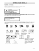
SYMBOLS AND DECALS Symbols and Decals These symbols are found on the machine and in the operator's manual. Study them carefully so that you know what they mean. WARNING! Xxxxxxx Xxxxx XXXX XXXXXXXX XXXXXX XX XXXXXXXX XXX X XX. XXXXX XXX XX, Used in this publication to notify the reader of a risk of personal injury or death, particularly if the reader should neglect to follow instructions given in the manual. IMPORTANT INFORMATION Xxxxxxx XXXX XXXXXXXX XXXX XXXXXX XXX XXX XX.
SYMBOLS AND DECALS Read Shut off engine Operators Manual & remove before key Keep a safe distance from the machine, performing any maintenance or Use on slopes no greater than 10 °. No Careful backing up, watch for other people, Careful going forward, watch for other people. passengers repair work. A A A i A A Whole Severing body of fingers & toes. exposure to thrown objects. Do not open or remove safety shields while engine is running.
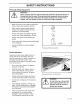
SAFETY INSTRUCTIONS Safety Instructions These instructions are for your safety. Read them carefully. This symbol means that important safety instructions need to be emphasized. It ARNING! concerns your safety. Z_ IMPORTANT: THIS CUTTING MACHINE IS CAPABLE OF AMPUTATING HANDS AND FEET AND THROWING OBJECTS. FAILURE TO OBSERVE THE FOLLOWING SAFETY INSTRUCTIONS COULD RESULT IN SERIOUS INJURY OR DEATH.
SAFETY INSTRUCTIONS Disengage blades when not mowing. Shut off engine and wait for all parts to come to a complete stop before cleaning the machine, removing the grass catcher, or unclogging the discharge guard. Operate machine only in daylight or good artificial light. Do not operate the machine while under the influence of alcohol or drugs. Watch for traffic when operating near or crossing roadways. Use extra care when loading or unloading the machine into a trailer or truck.
SAFETY INSTRUCTIONS Personal Safety Equipment WARNING! When using the machine, approved personal protective equipment (shown in illustrations) shall be used. Personal protective equipment cannot eliminate the risk of injury but it will reduce the degree of injury if an accident does happen. Ask your retailer for help in choosing the right equipment. Make sure that you have first aid equipment close at hand when using the machine. Never use the machine when barefoot.
SAFETY INSTRUCTIONS Use extra care while operating machine with grass catchers or other attachments; they can affect the stability of the machine. Do not use on steep slopes. Do not try to stabilize the machine by putting your foot on the ground. Do not mow near drop-offs, ditches, or embankments. The machine could suddenly roll over if a wheel is over the edge or if the edge caves in. Children 801/ Tragic accidents can occur if the operator is not alert to the presence of children.
SAFETY INSTRUCTIONS Maintenance /_ The engine must not be started when the driver's floor plate or any protective plate for the mower deck's drive belt is removed. WARNING! Safe Handling of Gasoline To avoid personal injury or property damage, use extreme care in handling gasoline. Gasoline is extremely flammable and the vapors are explosive. Extinguish all cigarettes, cigars, pipes, and other sources of ignition. Use only approved gasoline container.
SAFETY INSTRUCTIONS the sun may otherwise cause the fuel to expand and overflow. General Maintenance Never operate machine in a closed area. Keep all nuts and bolts tight to be sure the equipment is in safe working condition. Never tamper with safety devices. Check their proper operation regularly. Keep machine free of grass, leaves, or other debris build-up. Clean oil or fuel spillage and remove any fuel-soaked debris. Allow machine to cool before storing.
SAFETY INSTRUCTIONS Acid in the eyes can cause blindness, contact a doctor immediately. Be careful when servicing the battery. Explosive gases form in the battery. Never perform maintenance on the battery when smoking or near open flames or sparks. The battery can explode and cause serious injury/damage. Ensure that nuts and bolts, especially the fastening bolts for the blade attachments, are properly tightened, torqued and that the equipment is in good condition. Do not modify safety equipment.
SAFETY INSTRUCTIONS run over or into anything. If necessary, make repairs before starting. Never make adjustments with the engine running. The machine is tested and approved only with the equipment originally provided or recommended by the manufacturer. Only use approved repair parts for the machine. The blades are sharp and can cause cuts and gashes. Wrap the blades or use protective gloves when handling them. Check the parking brake's functionality regularly. Adjust and service as necessary.
SAFETY INSTRUCTIONS Customer responsibilities • Read and observe the safety rules. • Follow a regular schedule in maintaining, caring for and using your mower. • Follow the instructions under "Maintenance" and "Storage" sections of this owner's manual. • This machine has no brain.
CONTROLS Controls This operator's manual describes the Husqvarna Zero Turn Rider. The rider is fitted with a Briggs and Stratton four-stroke engine developing 22-24 horse power. Transmission from the engine is made via two belt-driven hydrostat transaxles, one for each drive wheel. Using the left and right steering controls, the flow is regulated and thereby the direction and speed. 80E/ 648 Zero 12 11 10 9 8 7 Turn Rider 6 5 80/1 Locations of the controls Control Locations Page Page 1.
CONTROLS 1. Motion Control Levers The machine's speed and direction are continuously variable using the two steering controls. The steering controls can be moved forward or backward about a neutral position. Furthermore, there is a neutral position, which is locked if the steering controls are moved outward. When both controls are in the neutral position (N), the machine stands still.
CONTROLS 2. Seat adjustment knobs The seat can be adjusted lengthways. When making adjustments, loosen the four knobs under the seat pan, after which the seat can be moved backward or forward. Do not forget to tighten the knobs. cz Lengthways / adjustment 3. Fuses The fuses are located in the right front corner of the engine compartment. They are flat pin fuses of the same type used in automobiles. There are two fuses. Fuse ratings and functions: • 20 A, Primary fuse. • 7.5 A, Mower deck coupling.
CONTROLS 4. By pass linkages When pushing or pulling the mower, be sure to engage the IZT (lntegraded Zeroturn Transaxle) bypass linkages. The IZT bypass linkages are located on the rear of the frame, below the rear engine guard. i/ '\ // \ \ \ \ \\ © Raise the deck into the highest cutting position. © Pull the IZT bypass linkages out and into the slots and release so that it is held in the bypass position. To reengage the lZT's to drive, reverse the above procedure. \ 8011 721 1.
CONTROLS 5. Refueling The machine has one fuel tank, just behind the seat. The tank capacity is 3 gallons (11.4 liters). The engine will run on a minimum of 85-octane unleaded gasoline (no oil mix). Environmentally adapted alkylate gasoline can be used. See also Technical Data concerning ethanol fuel. Methanol fuel is not allowed. WARNING! Gasoline is highly flammable. Observe caution and fill the tank outdoors (see the safety rules).
CONTROLS 7. Ignition Switch The ignition key is placed on the driver's panel and is used to start and stop the engine. IMPORTANT INFORMATION Do not run the starter for more than five seconds each time. If the engine does not start, wait about 10 seconds before retrying. 80/1 748 Ignition key and hour meter 8. Choke Control The choke mode is used for cold starts in order to provide the engine with a richer fuel mixture. The Throttle control is equipped with a choke detent.
CONTROLS 10. Hour Meter The hour meter displays the total operating time. It will flash CHG OIL (Change Oil) at 50 hour intervals. The flash duration is one hour before and one hour after the interval. The CHG OIL icon will come on and shut off automatically. The hour meter can not be manually reset. 80/1 749 801/ 481 Hour meter 11. Parking Brake IMPORTANT INFORMATION The machine must be stopped before activating the parking brake. The parking brake is found below the front of the seat.
CONTROLS 12. Cutting height pedal The deck cutting height is obtained by pressing the foot pedal forward to lift the deck. To lower the deck, you apply pressure to the top side of the foot pedal and allow it to pivot while allowing the lift arm to rotate to the rear of the unit. To stop in a desired cutting position, rotate the foot pedal down into the notch in the height plate. The cutting height range is from 1 1/2" (38 mm) to 5" (127 mm) in 1/2" (13 mm) increments.
OPERATION Operation Read "Safety Instructions" section and following pages, if you are unfamiliar with the machine. Training Zero turn mowers are far more manueverable than typical riding mowers due to their unique steering capabilities. We suggest when first operating the mower, use a reduced throttle speed and reduced ground speed by NOT moving control levers to the furthest forward or reverse positions during initial operation, or until operator becomes comfortable with controls.
OPERATION Before Starting Read the sections Safety Instructions and Controls before starting the machine. Perform the daily maintenance before starting (see Maintenance Schedule in the Maintenance section). Check that there is sufficient fuel in the fuel tank. • Adjust the seat to the desired position. The following conditions must be fulfilled before the engine can be started: • The driver must be seated on the seat. The blade switch for engaging the mower blades must be depressed.
OPERATION . Disengage the mower blades by depressing the blade switch. i .................. 80¸11 668 5. Depress the control Steering controls for disengaging the mower deck Move the steering controls outward to the locked (outer) neutral position. 801/ neutral . 7. in the outward, 489 locked position Move the throttle to the middle position. If the engine is cold, the throttle control should be pushed forward to its choke position.
OPERATION Press in and turn the ignition key to the start position. 80/1 742 Turn to the start position When the engine starts, immediately release the ignition key back to the run position. IMPORTANT INFORMATION Do not run the starter for more than 5 seconds each time. If the engine does not start, wait about 10 seconds before re-trying. 80E/ 743 Return to run position 10. Set the desired engine speed with the throttle.
OPERATION To start an engine with a weak battery WARNING! Lead-acid batteries generate explosive gases. Keep sparks, flame and smoking materials away from batteries. Always wear eye protection when around batteries. If your battery is too weak to start the engine, it should be recharged. (See "Battery" in the Maintenance Section. If "jumper cables" are used for emergency starting, follow this procedure: IMPORTANT INFORMATION Your mower is equipped with a 12-volt negative grounded system.
OPERATION Running 1. Release the parking brake by moving the lever downward. Your mower is equipped with an operator presence system. When the engine is running, any attempt by the operator to leave the seat without first setting the parking brake will shut off the engine. . Move the steering controls to the neutral position (N). Released 3. parking 80/1 481 801/ 753 80/1 669 brake Select the cutting height by the cutting height pedal. IMPORTANT INFORMATION \ The mower deck's anti-scalp roll
OPERATION Turning on the spot can be achieved by moving one control backward (behind the neutral position) and carefully moving the other steering control forward from its neutral position. Operating on hills Read the Safety Instructions "Driving on Slopes" in the "Safety Instructions". Do not drive up or down hills WARNING! with slopes greater than 10 degrees. And do not drive across any slopes. • The slowest speed possible should be used before starting up or down hills.
OPERATION Mowing Tips Observe and flag rocks and other fixed objects to avoid collisions. WARNING! Begin with a high cutting height and reduce it until the desired mowing result is attained. Clear the area of objects such as rocks, toys, wire, etc., which could be picked up and throw by the blades. The average lawn should be cut to 2 1/2" (64 mm) during the cool season and over 3" (76 mm) during the hot months. For healthier and better looking lawns, mow often after moderate growth.
OPERATION Stopping the Engine Allow the engine to idle a minute in order to attain normal operating temperature before stopping it, if it has been worked hard. Avoid idling the engine for longer periods, as there is a risk of the spark plugs fouling. 1. Disengage the mower deck by depressing the blade switch. Disengage 2. Raise the mower deck by depressing the pedal forward to the transport position. 3. When the machine is standing still, activate the parking brake by pulling the lever upward. 4.
OPERATION Moving by Hand WARNING! No adjustments or maintenance to be carried out unless: - the engine stopped, - the ignition key has removed, - the parking brake is on. When pushing or pulling the mower, be sure to engage the IZT (lntegraded Zeroturn Transaxle) bypass linkages. The tZT bypass linkages are located on the rear of the frame. /' \ \ /' • \ // ,\ \ // Raise the deck into the highest cutting position. \ © © 80/1 1.
MAINTENANCE Maintenance Maintenance Schedule The following is a list of maintenance procedures that must be performed on the machine. For those points not described in this manual, visit an authorized service workshop. An annual service carried out by an authorized service workshop is recommended to maintain your machine in the best possible condition and to ensure safe operation. Read "Maintenance" • in the Safety Instructions section.
MAINTENANCE Maintenance Page Daily mainte- Weekly mainte- At least nance nance once Before After each Maintenance interval in hours 25 50 100 300 year Check/adjust throttle cable 39 Check the condition of belts, belt pulleys, etc.
MAINTENANCE Battery Your mower is equipped with a maintenance free battery and does not need servicing. However, periodic charging of the battery with an automotive type battery charger will extend its life. • Keep battery and terminals clean. • Keep battery bolts tight. • Recharge at 6-10 amperes for 1 hour To clean battery and terminals Corrosion and dirt on the battery and terminals can cause the battery to "leak" power. 1. Open terminal access doors. 2.
MAINTENANCE Ignition System The engine is equipped with an electronic ignition system. Only the spark plug requires maintenance. For recommended spark plug, see Technical Data. . Remove the ignition cable boot and clean around the spark plug. 2. Remove the spark plug with a spark plug socket wrench. 3. Check the spark plug. Replace the spark plug if fouled, the electrodes are burned and if the insulation is cracked or IMPORTANT INFORMATION Fitting the wrong spark plug type can damage the engine.
MAINTENANCE Checking the Safety System The machine is equipped with a safety system that prevents starting or driving under the following conditions. The engine can only be started when: 1. The mower deck is disengaged. 2. The steering controls are in the outer, locked neutral position. 3. The driver is sitting in the driver's seat. 4. The parking brake is on. Make daily inspections to ensure that the safety system works by attempting to start the engine when one of the conditions is not met.
MAINTENANCE Checking the Engine's Cooling Air Intake Check that the engine's cooling air intake is free from leaves, grass, and dirt. If the cooling air intake is clogged, engine cooling deteriorates, which can lead to engine damage. 80/1 Check Checking and Adjusting Throttle Cable and clean the cooling 49/ air intake the Check that the engine responds to throttle increases and that a good engine speed is attained at full throttle. .......... \ J If doubts arise, contact the service workshop.
MAINTENANCE Replacing the Air Filter If the engine seems weak or runs unevenly, the air filter may be clogged. If run with a dirty air filter, the spark plug can become fouled. For this reason, it is important to replace the air filter regularly (see the heading Maintenance Schedule for the proper service interval). IMPORTANT INFORMATION Operating the engine with loose damaged air cleaner components could allow unfiltered air into the engine, causing premature wear and failure.
MAINTENANCE Replacing the Fuel Filter Replace the line-mounted fuel filter every 100 hours (once per season) or more regularly if it is clogged. Replace the filter as follows: 1. Move the hose clamps away from the filter. Use flat-nosed pliers. 2. Pull the filter loose from the hose ends. 3. Push the new filter into the hose ends. Position the filter with the "FLOW" arrow pointing up toward the carburator. If necessary, a soap solution can be applied to the filter ends to ease mounting. 4.
MAINTENANCE Checking the V-belts WARNING! No adjustments or maintenance to be carried out unless: • The engine is stopped. • The ignition key has been removed. • The parking brake is on. Deck belt V-belts are not adjustable. Replace belts if they begin to slip from wear. Deck belt removal Idler arm is spring loaded. Have a WARNING! tight grip on idler arm or ratchet and release slowly. -- Park on a level surface. Apply parking brake.
MAINTENANCE Deck belt installation NOTE: For ease in installing the deck belt, refer to the routing decal on bottom of seat. • Wrap the deck belt around the electric clutch pulley that is located on the engine shaft. Route the belt forward between the EZT (E-Series Zeroturn Transaxles) and up onto the deck. Place belt around spring loaded idler pulley, between the pulley and guide. Secure bolt and nut.
MAINTENANCE EZT belt To replace EZT (E-Series Zeroturn Transaxle) belt Park the mower on a level surface. Engage the parking brake. EZT belt removal NOTE: Be careful not to damage the fan blades on the EZT's as this can affect cooling or damage the EZT's Remove the deck belt (see to replace deck belt in this section of the manual). © Unplug clutch from wiring harness. Remove bolt from center of clutch and slide clutch off of engine shaft.
MAINTENANCE Checking the Blades In order to attain the best mowing effect, it is important that the blades are well sharpened and not damaged. 80E/ 604 Check the blades Bent or cracked blades or blades with large nicks should be replaced. Check the blade mounts. IMPORTANT INFORMATION The sharpening of blades should be carried out by an authorized service workshop. Damaged blades should be replaced when hitting obstacles that result in a breakdown.
MAINTENANCE • Install new or re-sharpened blade with stamped "GRASS SIDE" facing towards ground/grass (down) or "THIS SIDE UP" facing deck and cutter housing. Install and tighten blade bolt securely. Torque blade bolt to 27-35 ft/Ib (35-45 Nm). IMPORTANT INFORMATION Special blade bolt is heat treated. Replace with a Husqvarna bolt if required. Do not use lower grade hardware than specified. Adjusting the Mower Deck WARNING! Before performing any service or adjustment checklist: 1.
MAINTENANCE To level deck Adjust the deck while the mower is on a level surface. Make sure the tires are inflated to the correct pressure. See "Technical Data" under Transmission. If tires are under or over inflated, you can not properly adjust your deck. NOTE: It may be easier to adjust the front lift linkages by removing the floor pan before any adjustments are made. Side-to-side adjustment 1. Raise the deck into the four inch 4" (102 mm) cutting position. 2.
MAINTENANCE Front-to-back adjustment IMPORTANT INFORMATION Deck must be leveled side-to-side, prior to leveling front to back. If the following front to back adjustment is required, be sure to adjust both front and rear linkages equally so the deck will stay level side to side. To obtain the best cutting performance, the deck should be adjusted so the front tip of the blades are approximately 1/8" (3.2 mm) to 1/4" (6.5 mm) lower than the rear tip.
MAINTENANCE To adjust anti-scalp rollers Deck has anti-scalp rollers. Anti-scalp rollers are properly adjusted when they are just slightly off of the ground when the deck is at the desired cutting height in the operating position. Anti-scalp rollers then keep the deck in the proper position to help prevent scalping in most terrain conditions. \ ® IMPORTANT INFORMATION Adjust Anti-scalp rollers with the mower on a flat level surface.
MAINTENANCE Cleaning and Washing Regular cleaning and washing, especially under the mower deck, will increase the machine's lifespan. Make it a habit to clean the machine directly after use (after it is cooled), before the dirt sticks. Do not spray water on the top of the mower deck. Use compressed air to clean the top side of mower deck. Regulary clean deck and underside of deck, avoid spraying engine and electrical components with water.
LUBRICATION Lubrication Lubrication Schedule 2/12 1/52 1/365 25h 50h lOOh 200h 300h 80/1 Lubrication 673 schedule 12/12 Every 1/52 Every year Lubricate with grease gun Oil change 1/365 Every _ --_ Lubricate with oil can Week "_r _ Level check day Filter change General Remove the ignition key to prevent unintentional movements during lubrication. When lubricating with an oil can, it must be filled with engine oil.
LUBRICATION Lubricating the Cables If possible, grease both ends of the cables and move the controls to end stop positions when lubricating. Refit the rubber covers on the cables after lubrication. Cables with sheaths will bind if they are not lubricated regularly, tf a cable binds, it can disrupt operation. If a cable binds, remove the cable and hang it vertically. Lubricate it with light engine oil until the oil begins to escape from the bottom.
LUBRICATION 1. Place the machine on a flat surface. 2. Remove the yellow cap and fit a hose to the drain valve. IMPORTANT INFORMATION Used engine oil is a health hazard and must not be disposed of on the ground or in nature; it should always be disposed of at a workshop or appropriate disposal location. Avoid skin contact; wash with soap and water in case of spills. 3. Place a container under the engine where the hose from the oil drain valve exits. 4.
LUBRICATION Checking the oil level Check the oil level in the engine when the machine is standing level and the engine is stopped. Remove the dipstick, wipe it clean, and then replace it. The dipstick should be screwed into place. Take the dipstick out again and read the oil level. 801/ Remove 500 the dipstick The oil level shall lie between the markings on the dipstick. If the level is approaching the "ADD" mark, fill the oil to the "FULL" mark on the dipstick. Never fill above the "FULL" mark.
LUBRICATION 6. Check the oil level in the engine, fill if necessary. The oil filter holds 0.1 liters of oil. Transmission The transmission is maintenance free. There is no need for level checks or oil changes. If a leak occurs, replace the unit or contact your Husqvarna dealer.
TROUBLE SHOOTING GUIDE Trouble Shooting Guide Problem Cause The engine will not start. • The blade switch is engaged. The steering controls are not locked in the neutral position. The starter motor does not turn the engine over. • The driver is not sitting in the driver's seat. • The parking brake is not activated. • The battery is dead. • Contamination in the carburetor or fuel line. • The fuel supply is closed or the tap for the fuel tanks is in the wrong position.
TROUBLE SHOOTING GUIDE The engine seems weak. • Wrong fuel type. • Water in the fuel. • Clogged air filter. • Clogged air filter. • Defective spark plug. • Carburetor incorrectly adjusted. The engine overheats. Clogged air intake or cooling fins. Engine overloaded. Poor ventilation around engine. Defective engine speed regulator. Soot in the combustion chamber. Too little or no oil in the engine. Defective spark plug. Pre-ignition incorrect. Battery not charging.
TROUBLE SHOOTING GUIDE Uneven mowing results. The machine vibrates. English-58 Different air pressure in the tires on the left and right sides. • Bent blades. • The suspending for the mower deck is uneven. • The blades are blunt. • Driving speed too high. • The grass is too long. • Grass collected under the mower deck. • The blades are loose. • The blades are incorrectly balanced. • The engine is loose.
STORAGE Storage To ready the machine for storage, follow these steps: Winter 1. Thoroughly clean the machine, especially under the mower deck. Touch up damage to the paint and spray a thin layer of oil on the underside of the mower deck to avoid corrosion. 2. Inspect the machine for worn or damaged parts and tighten any nuts or screws that may have become loose. Storage At the end of the mowing season, the machine should be readied for storage (or if it will not be in use for longer than 30 days).
WIRING DIAGRAMS Wiring diagram 6. Seat unoccupied 11. Brake switch 8. Blade OFF pos. J 14-15. switch Motion ill, in OFF control position levers OUT 1. Battery 2. Accessory outlet 3. Key switch 4. To engine 16 pigtail 5. Hour meter 6. Seat switch 7. Run relay 14 I'_c_ LO---ZL>_ 8. Blade switch 9. Brake relay 10. Electric clutch 1 1. Brake switch 12. Start relay 13. Starter solenoid 14. Left motion control lever 15. Right motion lever control 16.
TECHNICAL Technical DataTechnical DATA Data Z4218 Z4219 Engine Manufacturer Kohler Briggs Type Courage Intek Single Power 18 hp / 13.4kW 19 hp / 14.2kW Lubrication Pressure and Stratton with oil filter Oil capacity excl filter 1.6 qt / 1.5 liter 1.5 qt / 1.4 liter Oil capacity incl filter 1.7 qt / 1.6 liter 1.6 qt / 1.
TECHNICAL DATA Z4218 Z4219 Equipment Cutting width 42"/107cm 42"/107cm Cutting height 1.5"- 4" / 3.8 - 10.2 cm 1.5"- 4"/3.8 0 0 2 2 21" / 533 mm 21" / 533 mm No No Standard Standard No No Hour meter Standard Standard Blade engagement 85 ft/Ib Warner 85 ft/Ib Warner Deck construction 12 gauge, Uncut circle Number Blade of blades length Nose rollers Sprung standard Hinged armrests seat stamped steel 12 gauge, 2.6 acres/h 10530 m2/h 485 Ibs/220 kg - 10.
TECHNICAL DATA Z4824 Z5426 Engine Manufacturer Briggs Type Intek single ELS twin Power 24 hp/17.65kW 26 hpi and Stratton Lubrication Briggs Pressure and Stratton 19.4kW with oil filter Oil capacity excl filter 1.5 qt / 1.4 liter 1.5 qt / 1.4 liter Oil capacity incl filter 1.6 qt / 1.5 liter 1.6 qt / 1.5 liter Engine oil (See viscocity SAE 5W30, 10W30 SAE 30 Mineral digram) Synt.
TECHNICAL DATA Z4824 Z5426 Equipment Cutting width 48"/122cm Cutting height 1.5"- 4" / 3.8 - 10.2 cm Uncut circle Number of blades 54"/122cm 0 0 3 3 Blade length 16 1/2" / 419mm Nose rollers Yes Yes Standard Standard No No Hour meter Standard Standard Blade engagement 85 ft/Ib Warner 85 ft/Ib Warner Deck construction 12 gauge, Sprung standard Hinged armrests seat stamped steel 10 gauge, stamped Productivity Productivity Overall 2.
TECHNICAL DATA Accessories Head lights BioClip attachment (Mulch clip) Collection system Torque Specifications -Engine crankshaft bolt 50 ft/Ib (67 Nm) -Deck pulley bolts 45 ft/Ib (61 Nm) -Lug nuts 75 ft/Ib (100 Nm) -Blade bolt 27-35 ft/Ib (35-45 Nm) -Standard IA" fasteners 9 ft/Ib (12 Nm) -Standard 5/16" fasteners 18 ft/Ib (25 Nm) -Standard 3/8" fasteners 33 ft/Ib (44 Nm) -Standard 7/16" fasteners 52 ft/Ib (70 Nm) -Standard ½" fasteners 80 ft/Ib (110 Nm) When this product is worn out a
CONFORMITY Conformity CERTIFICATES Certificates USA requirements Labels are placed on the engine and/or in the engine compartment stating that the machine will fulfill the requirements. This is also applicable to special requirements for any of the states, (Californian emission rules etc.). Do not remove any of these labels. Certificates can also be supplied with the machine at delivery or written in the Engine manual. Take care of them as valuable documents.
SERVICE JOURNAL Service Journal Action Delivery Date, mtr reading, stamp, sign Service 1. Charge the battery. 2. Adjust the tire pressure of all wheels to 1 bar (15 PSI). 3. Mount the steering controls in the normal position. 4. Connect the to the cables for the seat's safety switch. 5. Check that the right amount of oil is in the engine. 6. Adjust the position of the steering controls. 7. Fill with fuel. 8. Start the engine. 9. Check that there is drive to both wheels. 10.
SERVICE JOURNAL After the First 5-8 Hours 1. Change engine oil.
SERVICE JOURNAL Action 25-Hour Date, mtr reading, stamp, sign Service 1. Sharpen/Replace 2. Lubricate the caster wheels. 3. Check the tire pressures. 4. Check battery with cables. 5. Check/clean the engine's cooling air intake. 6. Clean the air cleaner's pre-filter (foam). mower blades if required.
SERVICE JOURNAL Action 50-Hour Date, mtr reading, stamp, sign Service 1. Perform the 25-hour service. 2. Clean/replace the air cleaner's filter cartridge (paper filter) (shorter intervals for dusty operating conditions). . Change the engine oil. 4. Inspect muffler/spark arrester. 5. Check/adjust the parking brake.
SERVICE JOURNAL Action 100-Hour Date, mtr reading, stamp, sign Service 1. Perform the 25-hour service. 2. Perform the 50-hour service. 3. Change the engine oil filter. 4. Clean/replace the spark plug. 5. Clean the cooling fins on the engine and transmission. 6. Check V-belts. 7. Check tighten caster wheel axle bolts (every 200 hours). 8. Change the air filter's paper cartridge.
SERVICE JOURNAL Action 300-Hour Date, mtr reading, stamp, sign Service 1. Inspect the machine. Come to agreement with the customer as to which additional work is to be carried out. 2. Perform the 25-hour service. 3. Perform the 50-hour service. 4. Perform the 100-hour service. 5. Check/adjust the mower deck. 6. Clean the combustion chamber and grind the valve seats. 7. Check the engine valve clearance. 8. Replace the air cleaner's pre-fllter (foam).
SERVICE JOURNAL Action Date, mtr reading, stamp, sign At Least Once Each Year 1. Clean the engine's cooling air intake (25 hours). 2. Replace the air cleaner's pre-filter (Oil-foam) (300 hours). 3. Replace the air filter's paper cartridge. 4. Change the engine oil (50 hours). 5. Replace the engine oil filter (100 hours). 7. Check/adjust the cutting height. 8. Check/adjust the parking brake (50 hours). 9. Clean/Change the spark plug (100 hours). 11. Clean the cooling fins (100 hours). 12.
113926Rir 06/05/06