Husqvarna m (YT Owner's Manual '7
SAFETY RULES Practices for Ride-On Safe Operation Mowers DANDER: THiS CUTTING MACHINE iS CAPABLE OF AMPUTATING HANDS AND FEET ANDTHROWING OBJECTS. FAILURE TO OBSERVE THE FOLLOWING SAFETY iNSTRUCTiONS COULD RESULT iN SERIOUS iNJURY OR DEATH. * WARNING: in order to prevent accidental starting when setting up, transporting, adjusting or making repairs, always disconnect spark plug wire and place wire where it cannot contact spark plug. * * * I _ _ U _t in n_se tractor.
SAFETY RULES Practices for Ride=On Safe Operation III. CHILDREN GENERAL SERVICE • Never operate machine in a closed area. • Keep all nuts and bolts tight to be sure the equipment is in safe working condition. • Never tamper with safety devices. Check their proper operation regularly. • Keep machine free of grass, leaves, or other debris build-up. Clean oil or fuel spillage and remove any fuelsoaked debris. Allow machine to cool before storing.
PRODUCT SPECIFICATIONS CUSTOMER Gasoline Capacity and type: 4 Gallons Unleaded Regular Oil Type (API-SG-SL): SAE 30 (above 32°F) SAE 5W-30 (below 32°F) Oil Capacity: W/Filter: W/O Filter: Spark Plug: (Gap: .040") Champion QC12YC Ground Speed (MPH): Forward: Reverse: • • 4.0 Pints 3.75 Pints 16 AMPS @ 3600 RPM Battery: AMP/HR: MIN. CCA: Case Size: Blade Bolt Torque: 45-55FT. LBS.
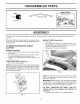
UNASSEMBLED PARTS Slope Sheet Key (2) Keys ASSEMBLY Your new tractor has been assembled at the factory with the exception of those parts left unassembled for shipping puposes. When right or left hand is mentioned in this manual, it means when you are in the operating position (seated behind the steering wheel). TO REMOVE TRACTOR CARTON UNPACK , SEAT (See Fig. 2) • Sit in seat.
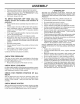
ASSEMBLY • • Release parking brake by depressing brake pedal. Place freewheel control in disengaged position to disengage transmission (See "TO TRANSPORT" in the Operation section of this manual). Roll tractor forward off skid. TO DRIVE TRACTOR OFF eration section for location controls) • • • • • • • • ,/CHECKL BEFORE YOU OPERATE YOUR NEW TRACTOR, WE WISH TOASSURE THATYOU RECEIVE THE BEST PERFORMANCE AND SATISFAC TION FROM THIS QUALITY PRODUCT. PLEASE REVIEW THE FOLLOWING CHECKLIST.
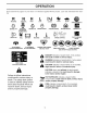
OPERATION These symbols may appear on your tractor or in literature supplied with the product. ing.
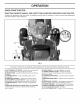
OPERATION KNOW YOU R TRACTOR READ THIS OWNER'S MANUAL Compare the illustrations with your tractor Save this manual for future reference. AND SAFETY to familiarize RULES BEFORE yourself OPERATING with the locations of various YOUR TRACTOR controls and adjustments. )3026 FiG. 3 Our tractors conform to the applicable safety standards (A) ATTACHMENT LIFT LEVER - Used to raise and lower the mower or other attachments mounted to your tractor.
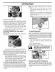
OPERATION The operation of any tractor can result in foreign objects thrown into the eyes, which can result in severe eye damage. Always wear safety glasses or eye shields while operating your tractor or performing any adjustments or repairs. We recommend standard safety glasses or a wide vision safety mask worn over spectacles. HOW TO USE YOUR TRACTOR TO SET PARKING BRAKE(See IMPORTANT: Leaving the ignition switch in any position other than "STOP" will cause the battery to discharge and go dead. Fig.
OPERATION NOTE: Adjust gauge wheels with tractor on a flat level surface. • • • Adjust mower to desired cutting height (See "TO ADJUST MOWER CUTTING HEIGHT" in this section of manual). With mower in desired height of cut position, gauge wheels should be assembled so they are slightly off the ground. Install gauge wheel in appropriate hole. Tighten securely. Repeat for all, installing gauge wheel in same adjustment hole. FiG.
OPERATION _I_WARNING: Backing up with the attachment clutch engaged while mowing is strongly discouraged. Turning the ROS "ON", to allow reverse operation with the attachment clutch engaged, should only be done when the operator decides it is necessary to reposition the machine with the attachment engaged. Do not mow in reverse unless absolutely necessary. Transmission USING THE REVERSE OPERATION SYSTEM Only use if you are certain no children or other bystanders will enter the mowing area.
OPERATION Release the parking brake and let the brake slowly return to operating position. Allow one minute for transmission to warm up. This can be done during the engine warm up period. The attachments can be used during the engine warm-up period after the transmission has been warmed up and may require the choke control be pulled out slightly. CAUTION: Alcohol blended fuels (called gasohol or using ethanol or methanol) can attract moisture which leads to separation and formation of acids during storage.
OPERATION MOWING TiPS • Mower should be properly leveled for best mowing performance. See"TO LEVEL MOWER HOUSING" in the Service and Adjustments section of this manual. The left hand side of mower should be used for trimming. Drive so that clippings are discharged onto the area that has been cut. Have the cut area to the right of the machine. This will result in a more even distribution of clippings and more uniform cutting.
MAINTENANCE m m BEFORE EACH USE MAINTENANCE SCHEDULE T Check Brake Check Tire Pressure R Check A Check Operator Operation Presence for Loose C Check/Replace & ROS Systems Fasteners Mower v' v' v" v" EVERY 8 HOURS EVERY 25 HOURS Check Battery R Clean Battery Chanqe Change Air Filter G Clean Air Screen i," _ t," v" v" v' v" v' v" V_1,2 Oil (with oil filter) Engine Oil (without Clean v' VF1,2 oil filter v' I Inspect Muffler/Spark Arrester N Replace Oil Filter (I
MAINTENANCE TRACTOR CAUTION: Use onlya replacement blade approved by the manufacturer of your tractor. Using a blade not approved by the manufacturer of your tractor is hazardous, could damage your tractor and void your warranty. Always observe safety rules when performing any maintenance. BRAKE OPERATION If tractor requires more than five (5) feet to stop at highest speed in highest gear on a level, dry concrete or paved surface, then brake must be serviced.
MAINTENANCE V-BELTS Remove yellow cap from end of drain valve and install the drain tube onto the fitting. Check V-belts for deterioration and wear after 100 hours of operation and replace if necessary. The belts are not adjustable. Replace belts if they begin to slip from wear. TRANSAXLE OIL DRAIN VALVE COOLING The transmission fan and cooling fins should be kept clean to assure proper cooling. Do not attempt to clean fan or transmission while engine is running or while the transmission is hot.
MAINTENANCE IN=LINE FUEL FILTER • (See Fig. 16) The fuel filter should be replaced once each season. If fuel filter becomes clogged, obstructing fuel flow to carburetor, replacement is required. • With engine cool, remove filter and plug fuel line sections. Be sure there are no fuel line leaks and clamps are properly positioned. Immediately wipe up any spilled gasoline. CLEANING Clean engine, battery, seat, finish, etc. of all foreign matter.
SERVICE AND ADJUSTMENTS CAUTION: After rear lift links are disconnected, the attachment lift lever will be spring loaded. Have a tight grip on lift lever when changing position of the lever. • • Turn tractor steering wheel to the left as far as it will go. Slide mower out from under right side of tractor. TO iNSTALL MOWER (See Figs. 18=22) FiG. 18 Be sure tractor is on level surface and engage parking brake. • Lower attachment lift lever to it's lowest position. CAUTION: Lift lever is spring loaded.
SERVICE AND ADJUSTMENTS • • VISUAL SIDE-TO-SIDE ADJUSTMENT (See Fig. 23) • With all tires properly inflated and if your lawn appears unevenly cut, determine which side of mower is cutting lower. Disengage belt tension rod (K) from locking bracket (L). Install belt onto engine clutch pulley (M). IMPORTANT: Check belt for proper routing in all mower pulley grooves. NOTE: As desired, you can raise the low side of mower or lower the high side. • Go to side of mower you wish to adjust.
SERVICE AND ADJUSTMENTS PRECISION SIDE-TO-SIDE ADJUSTMENT (See Fig. 24) • With all tires properly inflated, park tractor on level ground or driveway. ] CAUTION: Blades are sharp. Protect your hands with gloves and/or wrap blade with heavy cloth. | 1 Raise mower to its highest position. At both sides of mower, position blade at side and measure the distance (A) from bottom edge of blade to the ground. The distance should be the same on both sides.
SERVICE AND ADJUSTMENTS • [_ • Joaded. Have a tight grip on rod and CAUTION: Belt tension rod is spring engage sJowJy. • Raise attachment lift lever to highest position. • Reinstall anti-rotation link (B) on right side of tractor. Tighten securely. Reconnect clutch harness (A). Make sure belt is in all pulley grooves and inside all belt guides and keepers. install mower (See "TO iNSTALL MOWER" in this section of manual). FiG. 27 TO REPLACE MOTION DRIVE BELT (See Fig.
SERVICE AND ADJUSTMENTS • • Repair tire and reassemble. On rear wheels only: align grooves in rear wheel hub and axle. Insert square key. • Replace washers and snap retaining ring securely in axle groove. • Replace axle cover. NOTE: To seal tire punctures and prevent flat tires due to slow leaks, tire sealant may be purchased from your local parts dealer. Tire sealant also prevents tire dry rot and corrosion. Pq WEAK OR DEAD BATTERY FIG. 32 REPLACING WASHERS BATTERY (See Fig.
SERVICE AND ADJUSTMENTS TO REPLACE • • • • HEADLIGHT TO REMOVE HOOD AND GRILL (See Fig. 34) BULB Raise hood. Pull bulb holder out of the hole in the backside of the grill. Replace bulb in holder and push bulb holder securely back into the hole in the backside of the grill. Close hood. iNTERLOCKS • Raise hood. • Unsnap headlight wire connector. Stand in front of tractor. Grasp hood at sides, tilt toward engine and lift off of tractor. To replace, reverse above procedure.
STORAGE ENGINE Immediately prepare your tractor for storage at the end of the season or if the tractor will not be used for 30 days or more. FUEL SYSTEM IMPORTANT: iT iS IMPORTANTTOPREVENTGUM DEPOSITS FROM FORMING IN ESSENTIALFUEL SYSTEM PARTSSUCH AS CARBURETOR, FUEL FILTER, FUEL HOSE, OR TANK DURING STORAGE. ALSO, EXPERIENCE INDICATESTHAT ALCOHOL BLENDED FUELS (CALLED GASOHOL OR USING ETHANOLOR METHANOL) CAN ATTRACTMOISTUREWHICH LEADSTOSEPARATIONAND FORMATIONOFACIDS DURING STORAGE.
TROUBLESHOOTING PROBLEM CAUSE Will not start Hard tostart Engine will not turn over Engine clicks start but will not Loss of power Excessive vibration POINTS CORRECTION 1. Out of fuel. 1. Fill fuel tank. 2. 3. 4. 5. 6. 7. 8. Engine not "CHOKED" properly. Engine flooded. Bad spark plug. Weak or dead battery. Dirty air filter. Dirty fuel filter. Water in fuel. 2. 3. 4. 5. 6. 7. 8. See "TO START ENGINE" in Operation section. Wait several minutes before attempting to start. Replace spark plug.
TROU LESHOOTING P PROBLEM CAUSE CORRECTION Engine dies when tractor is shifted 1. 1. Reverse operation system (ROS) is not "ON" while mower or other attachment is engaged. into reverse Engine continues to run when operator leaves seat with attachment dutch engaged 1. Faulty operator-safety Poorcut-uneven 1. 2. Mower blades rotate will net Poor grass discharge NTS Turn ignition key to ROS "ON" position. See Operation section. presence control system. 1.
TRACTOR - MODEL NO. 917.279200 (YTH2448T) SCHEMATIC 02929-194276 Regulated-Tex BATTERY SOLENOID _ , STARTER ; I I [ WHETE ..... I==- w.... "J u , I O',_l I ' IRoo I ICL_AKEII _ I __ I _PEDA_L UP_ I 'B.... I ....... I I II _ CLUTCH I I v r, ,_O_ 1 ELECTRIC i .... ,_1 O I Ii BLACK GRAY A 1 EVERSE SWITCH 1 ..... r_ --22' ..... FIY I ..... h I n31 I SEAT SWITCH I I (NOTOCCUPIED) I BLL_C _ I JUNCTION -J _\.....
TRACTOR - MODEL NO. 917.279200 (YTH2448T) ELECTRICAL .... 22 / 41 \ 'I J I I I I I I I I I 42 33 34 \27_ 16 29 194276D 1"t I t I 28
TRACTOR - MODEL NO. 917.279200 (YTH2448T) ELECTRICAL KEY NO. 1 2 8 16 21 22 24 25 26 27 28 29 30 33 34 40 41 42 43 46 50 55 59 71 90 91 99 100 PART NO.
TRACTOR - MODEL NO. 917.
TRACTOR - MODEL NO. 917.279200 (YTH2448T) CHASSIS KEY NO. 5 14 15 18 25 34 37 58 68 99 130 139 150 152 156 161 162 165 175 176 177 178 180 181 182 184 PART NO.
TRACTOR - MODEL NO. 917.
TRACTOR - MODEL NO. 917.279200 (YTH2448T) DRIVE KEY NO. 2 15 17 26 29 33 35 37 42 49 50 51 52 56 64 70 74 80 92 116 125 143 148 159 160 161 162 163 166 167 PART NO.
TRACTOR STEERING ASSEMBLY - MODEL NO. 917.279200 (YTH2448T) 26 63 19 I UI 60 57 63 67 62 \ steering-tex / : 4-husq 13 KEY NO. PART NO. DESCRiPTiON 1 2 4 5 6 7 8 9 13 14 15 16 19 21 22 26 28 35 45 532 19 39-43 532 19 59-68 532 19 47-43 532 19 47-44 532 12 49-31 532 12 17-48 812 O0 00-29 532 12 12-32 532 12 17-49 810 04 06-00 873 54 06-00 532 19 47-46 532 19 47-29 532 18 67-37 532 19 48-45 532 19 36-52 817 O0 06-12 532 19 47-32 8191838-12 Wheel, Steering Axle Asm., Front Spindle Asm.
TRACTOR - MODEL NO. 917.279200 (YTH2448T) ENGINE 18 ® 15 82 81 12 11 41 12 37 29 / engine-tex KEY NO. 1 2 9 11 12 15 18 20 21 22 28 29 31 37 41 42 43 45 62 69 I SPARK 10-vgt PART NO. 532 14 97-23 532 19 43-19 532 17 93-34 532 40 29-80 532 19 34-99 532 19 42-67 532 17 83-85 5321916-11 532 19 15-96 532 40 11-35 532 13 71-80 532 14 50-06 532 12 34-87 532 12 61-97 810 04 07-00 532 15 02-80 873 51 04-00 532 14 66-29 532 16 53-91 DESCRIPTION Engine Briggs Model No.
TRACTOR - MODEL NO. 917.279200 (YTH2448T) SEAT ASSEMBLY 41 0 I seat-tex_5-husq KEY NO. 1 2 3 5 6 7 8 10 21 PART NO. 532 532 532 532 873 532 532 532 532 19 18 14 14 80 12 17 19 17 KEY NO. DESCRIPTION 75-26 01-66 06-75 50-06 06-00 41-81 18-77 69-77 18-52 Seat Bracket Pivot Fender Strap, Asm Fender Clip, Push In, Hinged Nut, Lock W/Ins. 3/8-16 unc Spring, Seat Cprsn Bolt 5/16-18 uncx 3/4 w/Sems Pan, Seat Bolt, Shoulder 5/16-18 37 40 41 43 44 PART NO.
TRACTOR - MODEL NO. 917.279200 (YTH2448T) DECALS 13 KEY NO. 1 2 3 5 6 8 9 13 PART NO. 532 532 532 532 532 532 532 532 WHEELS 2 40 40 17 17 18 19 14 18 16 15 2 \ DESCRiPTiON 21-04 21-28 05-63 85-02 96-84 87-85 50-05 89-25 Decal, Decal, Decal, Decal, Decal, Decal, Decal, Decal, Operator's Hood Insert Warning Caution Eng. HP Mower Sch. Battery Dnge/Poi Steering Whl AND TIRES 10 5 PART NO. 532 40 532 18 532 40 532 40 532 16 532 40 532 40 532 40 532 40 KEY NO. PART NO.
TRACTOR MOWER - MODEL NO. 917.279200 (YTH2448T) DECK 116 117 120 I 49 113/ /_ 26 194 27 7 I _- I 22_ I "/ 190 189 _'k / //' 190 15_(_ / //// / 14_ 13 / \ / / /' 48 Deck tex 6 8 38 \
TRACTOR MOWER KEY NO. 1 6 7 8 11 -13 14 15 18 20 21 22 24 25 26 27 29 30 31 32 33 39 43 46 47 PART NO. 532 532 532 532 532 532 532 532 532 872 532 873 532 532 532 532 532 532 532 532 532 532 532 532 532 532 - MODEL NO. 917.
TRACTOR MOWER - MODEL NO. 917.279200 (YTH2448T) LiFT /7 87 87 I 88 t 1 / 2 87 89 b--_ III "_, .__/ ,, f" -_ I lift-tex 3 KEY NO. PART NO. 2 3 7 10 87 88 89 532 532 532 532 532 532 819 19 19 19 19 19 19 19 _:_:_ '1 DESCRiPTiON 52-23 52-30 64-92 63-14 42-09 53-04 19-12 DESCRiPTiON 90 91 97 98 Shaft Asm., Lift Lever Asm.
SERVICE NOTES 41
SUGGESTED GUIDE FOR SIGHTING SLOPES FOR SAFE OPERATION ONLY RIDE UP AND DOWN HILL, NOT ACROSS HILL 15 DEGREES MAX. 1. Fold this page along dotted line indicated above. 2. Hold page before you so that its left edge is vertically parallel to a tree trunk or other upright structure. 3. Sight across the fold in the direction of hill slope you want to measure. 4. Compare the angle of the fold with the slope of the hill.
Husqvarna NTYSTATE SECTION 1: LIMITED WARRANTY SECTION 4: EXCEPTIONS Husqvarna Forest & Garden Company ("Husqvarna") warrants Husqvarna product to the original purchaser to be free from defects in material and workmanship from the date of purchase for the "Warranty Period" of the product as set forth below: This warranty shall be inapplicable to defects resulting from the following: (1)Accident, abuse, misuse, negligence and neglect, including stale fuel, dirt, abrasives, moisture, rust, corrosion, or
532 40 34-51 Rev. 1 01.09.06 VB/TR {_ Husqvarna Printed in U.S.A.