A SAFETY RULES A Safe Operation Practices for Ride-On Mowers DANGER: THIS CUTTING MACHINE IS CAPABLE OF AMPUTATING HANDS AND FEET AND THROWING OBJECTS, FAILURE TO OBSERVE THE FOLLOWING SAFETY INSTRUCTIONS COULD RESULT IN SERIOUS INJURY OR DEATH. WARNING: In order to prevent ac. accidental starting when setting up, transporting, adjusting or making repairs, always disconnect spark plug wire and place wire where it cannot contact spark plug.
A Hi. CHILDREN Tragic accidents can occur if the operator is not alert to the presence of children. Children are often attracted to the machine and the mowing activity.
PRODUCT SPECIFICATIONS Gasoline Capacity 3.0 Gallons and type: Unleaded Regular Oil Type (API-SG-GLY: SAE 30 (above 32°F) SAE SW-30 (below 32°F) Off Capacity: Wi Filter: &4 oz. WIQ Filter: B80 oz. Spark Plug: Champion QC12YC (Gap: 040") Ground Speed (MPH): Forward: 0-55 Averse: 0-24 Charging System: 16 AMPS @ 3600 RPM Battery: AMP HR: 35 MIN. CCA: 280 Case Size: UTR Blade Bolt Torque: 45-55FT LBS, CONGRATULATIONS on your purchase of a new tractor.
ASSEMBLED PARTS Slope Sheet Key = {1} il Drain Tube 2° (2) Keys ASSEMBLY Your new tractor has been assembled at the factory with the exception of those parts left assembled for shipping pulses, Whenrightorlefthand is mentioned in this manual. it means ADJUST SEAT (See Fig. 2} when you are in the operating position (seated behind the Si in seat. steering wheel).
ASSEMBLY » Roll tractor forward off skid TO DRIVE TRACTOR QFF SKID (See Operation section for location and function of controls) + Be sure all the above assembly steps have been completed, + Check engine off level and fill fuel tank with gasoline. «Place freewheel control in “transmission engaged” position {see "TO TRANSPORT" in Operation section of this manual}. + Sit on seat in operating position. depress brake pedal and set the parking brake, + Raise attachment lift lever to its highest position.
OPERATION These symbols may appear on your tractor or in literature supplied with the product. Learn and understand their mean Reverse NEUTRAL HIGH LOW FAST CHOKE IGNITION SWITCH 2. £0.2.
OPERATION KNOW YOUR TRACTOR READ THIS OWNER'S MANUAL AND SAFETY RULES BEFORE OPERATING YOUR TRACTOR Compare the Frustration with your tractor to familiarize yourself with the locations of various controls and adjustments. Save this manual for future reference. FIG.
OPERATION vision safety mask worn over spectacles. The operation of any tractor can result in foreign objects thrown into the eyes, which can result in severe eye damage. Always wear safety glasses or eye shields while operating our tractor of performing any adjustments or repairs. We recommend standard safety glasses or a wide HOW TO USE YOUR TRACTOR TO SET PARKING BRAKE (See Fig. 4) Your refract is equipped with an operator presence sensing switch.
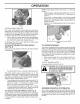
OPERATION FIG. 7 SYSTEM CHARACTERISTICS The cruise control should only be used while mowing or transporting on relatively smooth, straight surfaces. Other conditions such as trimming at slow speeds may cause the cruise control to disengage. Do not use the cruise control on slopes, rough terrain or while timing or muting. + With forward drive pedal depressed to desired speed, pull cruise control lever (J) up and hold while lifting your foot off the pedal, then release the lever.
OPERATION WARNING: Backing up with the attachment clutch engaged while mowing is strongly discouraged. Turning the ROS "ON*. to allow reverse operation with the attachment clutch engaged, should only be done when the operator decides it is necessary to reposition the machine with the attachment engaged. Do not mow in reverse unless absolutely necessary. USING THE REVERSE OPERATION SYSTEM Only use ff you are certain no children or other bystanders will enter the mowing area.
OPERATION CAUTION: Alcohol blended fuels (ailed gasohol or using ethanol or methanol} can attract moisture which leads to separation and formation of acids during storage. Acidic gas can damage the fuel system of an engine while in storage. Geoengineering problems, the fuel system should be emptied before storage of 30 days ov longer. Drain the gas tank, start the engine and let it run until the fue! lines and carburetor are empty. Use fresh fuel next season.
OPERATION MOWING TIPS + Mower should be properly leveled for best mowing performance. See “TO LEVEL MOWER HOUSING in the Service and Adjustments section of this manual, « The left hand side of mower should be used for trimming. « Drive so that clippings are discharged onto the area that has been cut.
MAINTENANCE BEFORE | EVERY REDOUND es Check Brake ration Check Tire Pressure [Check Operator Provence & ROS Stony: A |Check lov Loose Fasteners C [Check/Replace Mower Blades T |Lubrication Chart 0 [chock Battery Level Clean Battery and Terminals Check Trans axle Cooling Check Mower Levelness Check V-Belts heck Engine Of Level hang Engine Ol {with ofl filter: hang Engine Oil (without ofl filter, lean Air Screen | inspect Muffler/Spark Arrested N Replace Oil Fitter (if equip E [clean Engine Cooling Fins Repla
MAINTENANCE TRACTOR Always observe safety rules when performing any maintenance. BRAKE OPERATION if tractor requires more than five (5) feet to stop at highest speed in highest gear on a level, dry concrete or paved surface, then brake must be serviced.
MAINTENANCE + Coat terminals with grease or petroleum jelly. + Reinstall battery (See "REPLACING BATTERY" in the SERVICE AND ADJUSTMENTS section of this manual). V-BELTS Check V-belts for deterioration and wear after 100 hours of operation and replace if necessary. The belts are not adjustable. Replace belts if they begin to slip from wear, TRANS AXLE COOLING The transmission fan and cooling fins should be kept clean 0 brassiere proper cooling.
MAINTENANCE MUFFLER Inspect and replace corroded muffler and spark arrested (if equipped) as it could create a fire hazard and/or damage. SPARK PLUGS Replace spark plugs at the beginning of each mowing season or after every 100 hours of operation, whichever scours first, Spark plug type and gap setting are shown in “PRODUCT SPECIFICATIONS” section of this manual. IN-LINE FUEL FILTER (See Fig. 16) The fuel filter should be replaced once each season.
SERVICE AND ADJUSTMENTS WARNING: TO AVOID SERIOUS INJURY, BEFORE PERFORMING ANY SERVICE OR ADJUST MEETS: * Depress brake pedal fully and set parking brake. + Pace attachment clutch in “DISENGAGED” position. * Turn ignition key to “STIR” and remove key, * Make sure the blades and ail moving parts have completely stopped. + Disconnect spark plug wire from spark plug and place wire where it cannot come in contact ii TRACTOR TO REMOVE MOWER Place attachment clutch in “DISENGAGED" position.
SERVICE AND ADJUSTMENTS NOTE: Be sure mower side suspension arms (A) are pointing forward before sliding mower under tractor, « Slide mower under tractor until it is centered under tractor. «FIRST INSTALL ANTI-SWAY BAR (S). From right side of mower, insert anti-sway bar into hole in transmission bracket (T). FiG. 18 Pivot bar towards you and insert other end of bar into hole in rear mower bracket (D). Move mower as needed fo Insert bar.
SERVICE AND ADJUSTMENTS + Disengage belt tension rod (K) from locking bracket L. + Install belt onto engine clutch pulley (M). IMPORTANT: Check belt for proper routing in all maser pulley grooves, FiG. 23 Engage belt tension rod {K} on docking bracket (L). CAUTION: Belt tension rod is spring loaded. Have a tight grip on rod and engage slowly. «Raise attachment lift lever to highest position. + If necessary, adjust gauge wheels before operating mower as shown in the Operation section of this manual. FIG.
SERVICE AND ADJUSTMENTS TO LEVEL MOWER Make sure tires are properly inflated to the PSI shown on tires, If tires are over or under inflated, it may affect the appearance of your lawn and lead you to think the mower is not adjusted properly. VISUAL SIDE-TO-SIDE ADJUSTMENT (See Fig. 25) = With all tires proper inflated and if your lawn appears unevenly cut. determine which side of mower is cutting lower. NOTE: As desired, you can raise the low side of mower of lower the high side.
SERVICE AND ADJUSTMENTS TO REPLACE MOWER BLADE DRIVE BELT (SEE FIG. 28) MOWER DRIVE BELT REMOVAL + Park tractor an a level surface, Engage parking brake, «Lower attachment lift lever to its lowest position. © Disengage belt tension rod (K} from lock bracket (L). CAUTION: Belt tension rod is spring goaded. Have a firm grip on rod and release slowly.
SERVICE AND ADJUSTMENTS TO REPLACE MOTION DRIVE BELT Park the tractor on level surface, Engage parking brake, For assistance, there is a belt installation guide decal on bot torn side of left footrest. BELT REMOVAL 1. Remove mower (See “TO REMOVE MOWER" in this section of manual). NOTE: Observe entire motion drive belt and position of all belt guides and keepers. 2. Disconnect clutch wire harness (A), 3. Remove anti-rotation link (B} on right side of tractor, 4.
SERVICE AND ADJUSTMENTS TO START ENGINE WITH A WEAK BATTERY (See Fig. 30) WARNING: Lead-acid batteries generate explosive gases. Keep sparks, flame and smoking materials away from batteries. Always wear eye protection when around batteries. if your battery is too weak to start the engine, # should be recharged. {See "BATTERY" in the MAINTENANCE section of this manual). If “jumper cables” are used for emergency starting, follow this procedure: IMPORTANT: YOUR TRACTOR 13 EQUIPPED WITH A 12 VOLT SYSTEM.
§STORAGE ENGINE TO ADJUST THROTTLE CONTROL CABLE The throttle control has been preset at the factory and adjustment should not be necessary, If adjustment is necessary, see engine manual. TO ADJUST CHOKE CONTROL The choke control has been preset at the factory and adjustment should not be necessary, If adjustment is necessary, see engine martial. TO ADJUST CARBURETOR Your carburetor is not adjustable. If your engine does not operate properly due to suspected carburetor problems.
TROUBLESHOOTING POINTS PROBLEM CAUSE CORRECTION Will not start 1. Out of fug, 1. Fill fuel tank, 2. Engine not “CHOKED' properly. 2 See TO START ENGINE” in Opera 3. Engine flooded 3. Walt several minutes before ate 4. Bad spark plug 4. Replace spark plug 5. Weak or dead battery. 5. Recharge of replace battery, 6. Dirty alr fil & Irreplaceable al first 7. Dirty fuel fitter, 7. Replace fuse filter, 8. Water in fuel 8 Empty fuel tank and carburetor, refill tank with fresh gasoline and replace fuel filter 9.
TROUBLESHOOTING POINTS PROBLEM CAUSE CORRECTION Engine dies when tractor is shifted into reverse 1. Reverse operation system (ROS) is not "ON" while mower or other attachment is engaged Turn ignition key to ROS "ON" position. See Operation section Engine continues fo run when operator leaves seat with attachment clutch engaged 1 Faulty operator-safety presence control system ions. H not vice center, Check wiring. switches and nonce corrected, contact an authorized ser department. Foot cut uneven 1.
TRACTOR MODEL NUMBER YTH2348 (287560) DECALS KEY PART NO. OWN DWN NO. DESCRIPTION 532 40 21-04 Decal. Operators 532 40 28-32 Decal. Hood 532 41 00-56 Decal, Hood Panel 8D 532 40 21-28 Decal. Hood Top Insert 532 18 09-41 Decal, Customer Respond. 532 41 03-75 Decal, Replacement 532 40 44-84 Decal, Steering Wheel 532 40 88-41 Decal, Eng. HP 532 14 50-05 Decal, Battery Porringer WHEELS AND TIRES 1 TT—— KEY KEY Ch oh OND UTD GRD a 1 PART NO.
TRACTOR -MODEL NUMBER YTH2348 (287560) SCHEMATIC STARTER VGLUTGHBRAKE | : Ores 11 {PEDAL REVERSE SWITCH i engrossment 1g {NOT IN REVERSE) | § (DISENGAGED) § ‘ mmm soe seat switch NOT OCCUPIED! , Red JUNCTION I (CONNECTOR TS ! Poo 1 SHUNTING .
TRACTOR -MODEL NUMBER YTH2348 (287560) ELECTRICAL KEY PART NO, NO. DESCRIPTION 532 14 48-27 Battery 874 76 04-12 Bolt Hex Head x 3/4 532 18 64-81 Box Battery 532 17 61-38 Switch Interlock Push-in 582 18 37-59 Harness Socket Light W/4152.] 532 00 41-52 Bulb Light 532 40 02-53 Cable Bray 532 18 88-93 Cable Starter 532 17 51-58 Fuse 873 B1 04-00 Nut Reps Hex unc 532 14 54-91 Cable.
TRACTOR -MODEL NUMBER YTH2348 (287560) CHASSIS KEY PARTY NO. 183 188 NO. DESCRIPTION 532 40 50-12 Logo 532 40 87-01 Dash 532 18 65-3¢ Bolt Shoulder 532 40 18-24 Hood 532 18 89-07 Lens LH 532 40 88-07 Grille Asm.
TRACTOR -MODEL NUMBER YTH2348 (287560) DRIVE KEY PART NO. NOG. DESCRIPTION 1 532 40 53-84 Trans axle, TUFTER K46BT (See Trans axle breakdown) 2 532 12 35-83 Key 15 B19 13 13-16 Washer 13/32 x 13/16 532 41 36.
TRACTOR -MODEL NUMBER YTH2348 (287560) ENGINE KEY PART NO. NO. 1 ees 2 532 14 97-28 2 532 19 43-20 11 532 40 00-08 12 532 4050-87 15 532 4000-21 18 53219 42.67 20 5321783-85 21 53219 16-11 22 5321915-08 28 53240 11-35 20 5321371-80 31 532 14 50-08 a7 B321234-87 41 532126197 42 81004 07-00 45 87351 04-00 62 B32 14 86-20 69 53216 53-91 70 53215898-55 71 532 16 05-80 79 5321839-08 81 532 14 B-56 82 5321816-54 84 B17 0806-20 85 53217 38-37 87 80 58217 18-77 817 00 06-16 DESCRIPTION Engine B&S Model Na.
TRACTOR MODEL NUMBER YTH2348 (287560) STEERING ASSEMBLY KEY PART NO. NO. DESCRIPTION 1 532 19 39-43 Wheel, Steering 2 532 19 59-68 Axle Adm, Fran 4 532 40 30-87 Spindle Adm, LH 5 532 40 30-88 Spindle Adm, RH 8 532 12 49-31 Bearing.
TRACTOR -MODEL NUMBER YTH2348 (287560) SEAT ASSEMBLY sealer 7-gt KEY PART NO. HNO. DESCRIPTION 532 40 88-21 Seat 532 18 01-66 Bracket Pivot Fender 532 14 06-75 Strap, Asm Fender 873 80 06-00 Nut, Lock Wins. unc 532 12 41-81 Spring. Seat CPR 532 17 18-77 Bolt 5116-18 uncut 3/4 w/Sems 532 18 69-77 Pan, Seat 532 17 18-52 Bolt, Shoulder PO mk 00 OGD KEY PART NO. NO. DESCRIPTION 37 87380 05-00 Nut.
TRACTOR -MODEL NUMBER YTH2348 (287560) MOWER DECK KEY PARTY NO. NO. DESCRIPTION 1 532 40 35-82 Deck Amendment Mower 6 532 19 72-48 Over Mandrel LH 7 532 19 91-02 Over Mandrel RH 8 532 17 43-65 Bolt 7/16 Asm. Blade 1" 532 18 00-54 Blade High Lift -532 17 39-21 Blade Mulching 12 532 40 48-51 Rod Anti-Sway 13 532 18 72-81 Shaft Asm. w/lower Bearing 14 532 18 72-81 Housing, Mandrel 15 532 11 04-85 Bearing, Ball, Mandrel! 16 B19 13 13-12 Washer 13/23 x 13/16 x 1 2Ga. 17 87211 05-05 Bolt Carr.
TRACTOR -MODEL NUMBER YTH2348 (287560) MOWER LIFT KEY PART NO. NO. 2 532 19 52-23 3 532 19 52.31 7 532 10 64-92 10 532 1063-14 87 532104208 88 5321053-03 89 819101912 90 532194208 ot 532 19 51-81 87 B17 0606-12 98 532195284 DESCRIPTION Shaft Asm. Lift Lever Adm, Lift Bh Grip, Lever Spring Torsion Pin Cotter 7/16 Bow Tie Lock Spring Lift Assist Washer Clear Zinc Pin Cotter 5/18 Bow Tie Lock Link Lift Cusp Mower Rear Sower x .75 SGML Tap/R.Z Link Lift Cusp.
TRACTOR MODEL NUMBER YTH2348 (287560) TUFTER TRANS AXLE MODEL NUMBER K46BT KEY PART NO. NO.
TRACTOR MODEL NUMBER YTH2348 (287560) BRIGGS ENGINE MODEL NUMBER 445577, TYPE NUMBER 0755-E [036 EMISSIONS LABEL | 7 >) 304 i / Er 10400 616, 10268 3 Se 703 1013 2205 1035 965] : 9432 250 Cross o 15:3 sow 1022 486
TRACTOR MODEL NUMBER YTH2348 (287560) BRIGGS ENGINE MODEL NUMBER 445577, TYPE NUMBER 0755-E 121 CARBURETOR OVERHAUL KIT 276 — 1124¢ 1508 104 = 137 105f 1123 6339 2 1329 REPLACEMENT ENGINE [1330 REPAIR MANUAL 47
TRACTOR MODEL NUMBER YTH23438 (287560) BRIGGS ENGINE MODEL NUMBER 445577, TYPE NUMBER 0755-E KEY PART NO. NO.
KEY NO. 445 447 447A 467 474 505 501 510 513 523 524 525 526 544 552 852A 562 573 €01 £815 618 a17 £828 833 35 654 68 672 £01 895 897 708 78 726 741 742 750 783 788 789 BOA 797 ROTA 798 801 802 803 842 847 851 865 TRACTOR MODEL NUMBER YTH2348 (287560) BRIGGS ENGINE MODEL NUMBER 445577, TYPE NUMBER 0755-E PART NO.
SUGGESTED GUIDE FOR SIGHTING SLOPES FOR SAFE OPERATION ONLY RIDE UP AND DOWN HILL, NOT ACROSS HILL 15 DEGREES MAX. LL YUE EE EYL down the face of slopes, never across the face. Do not mow slopes greater than 15 degrees. Make turns gradually to prevent tipping or loss of control. Exercise extreme caution when changing direction on slopes. | 1 WARNING: To avoid serious injury, operate your tractor up and 1. Fold this page along dh dotted line indicated above. 2.