927SB Owner's Manual / 96193004400 / 2008-11
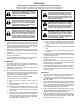
IMPORTANT Safe Operation Practices for Walk-Behind Snow Throwers This snow thrower is capable of amputating hands and feet and throwing objects. Failure to observe the following safety instructions could result in serious injury. WARNING: Snow throwers have exposed rotating parts, which can cause severe injury from contact, or from material thrown from the discharge chute. Keep the area of operation clear of all persons, small children and pets at all times including startup.
6. When cleaning, repairing or inspecting the snow thrower, stop the engine and make certain the collector/impeller and all moving parts have stopped. Disconnect the spark plug wire and keep the wire away from the plug to prevent someone from accidentally starting the engine. 7. Do not run the engine indoors, except when starting the engine and for transporting the snow thrower in or out of the building. Open the outside doors; exhaust fumes are dangerous. 8.
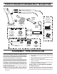
PARTS PACKED SEPARATELY IN CARTON (1) AUGER CONTROL ROD (1) TRACTION DRIVE CONTROL ROD (1) MULTIWRENCH (180684) (2) FLAT WASHERS (1) DISCHARGE CHUTE (1) POWER CORD (198563) (3) RETAINER SPRINGS (169675) ROTATOR HEAD MOUNTING (2) CARRIAGE BOLTS 3/8-16 x 2.
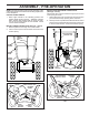
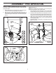
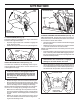
ASSEMBLY / PRE-OPERATION INSTALL TRACTION DRIVE CONTROL ROD (See Figs. 3 and 4) The traction drive control rod has the long loop on the end of the spring as shown. 1. Slide rubber sleeve up rod and hook end of spring into pivot bracket with loop opening down as shown. 2. With top end of rod positioned under left side of control panel, push rod down and insert top end of rod into hole in drive control bracket. Secure with retainer spring.
ASSEMBLY / PRE-OPERATION INSTALL DISCHARGE CHUTE / CHUTE ROTATOR HEAD (See Fig. 7) NOTE: The multi-wrench provided in your parts bag may be used to install the chute rotator head. 1. Place discharge chute assembly on top of chute base with discharge opening toward front of snow thrower. 2. Position chute rotator head over chute bracket. If necessary, rotate chute assembly to align square and pin on underside of chute rotator head with holes in chute bracket. 3.
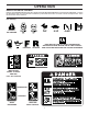
OPERATION KNOW YOUR SNOW THROWER READ THIS OWNER'S MANUAL AND ALL SAFETY RULES BEFORE OPERATING YOUR SNOW THROWER. Compare the illustrations with your snow thrower to familiarize yourself with the location of various controls and adjustments. Save this manual for future reference. These symbols may appear on your snow thrower or in literature supplied with the product. Learn and understand their meaning.
OPERATION SPARK PLUG SAFETY IGNITION KEY ENGINE OIL CAP WITH DIPSTICK AUGER CONTROL LEVER DISCHARGE CHUTE DRIVE CONTROL LEVER SPEED CONTROL LEVER GASOLINE FILLER CAP CHUTE DEFLECTOR CHOKE CONTROL TRACTION DRIVE CONTROL LEVER OIL DRAIN PLUG THROTTLE / ENGINE CONTROL DISCHARGE CHUTE RECOIL (AUXILIARY) STARTER HANDLE POWER CORD PLUG ELECTRIC START FUEL BUTTON SHUT-OFF VALVE PRIMER CHUTE DEFLECTOR KNOB CLEANOUT TOOL HANDLE KNOB MUFFLER NOTE: ITEMS ABOVE ARE SHOWN IN THEIR TYPICAL LOCATION ON THE
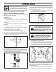
OPERATION The operation of any snow thrower can result in foreign objects thrown into the eyes, which can result in severe eye damage. Always wear safety glasses or eye shields while operating your snow thrower or performing any adjustments or repairs. We recommend standard safety glasses or a wide vision safety mask worn over spectacles. TO USE CHOKE CONTROL (See Fig. 11) The choke control is located on the engine. Use the choke control whenever you are starting a cold engine.
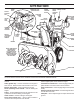
OPERATION HIGH POSITION DISCHARGE CHUTE CLEAN-OUT TOOL KNOB MOUNTING CLIP CHUTE DEFLECTOR LOW POSITION FIG. 15 FIG. 13 TO THROW SNOW (See Fig. 14) The auger rotation is controlled by the auger control lever located on the right side handle. • Squeeze auger control lever to handle to engage the auger and throw snow. • Release the auger control lever to stop throwing snow. AUGER CONTROL LEVER TO MOVE FORWARD AND BACKWARD (See Fig.
OPERATION TO ADJUST SKID PLATES (See Fig. 17) NOTE: The wrench provided in your parts bag may be used to adjust the skid plates. Skid plates are located on each side of the auger housing and adjust the clearance between the scraper bar and the ground surface. Adjust skid plates evenly to proper height for current surface conditions.
OPERATION TO START ENGINE • Be sure fuel shut-off valve is in the “OPEN” position. Your snow thrower engine is equipped with both a 120 Volt A.C. electric starter and a recoil starter. The electric starter is equipped with a three-wire power cord and plug and is designed to operate on 120 Volt A.C. household current. • Be sure your house is a 120 Volt A.C. three-wire grounded system. If you are uncertain, consult a licensed electrician. 6.
MAINTENANCE GENERAL RECOMMENDATIONS The warranty on this snow thrower does not cover items that have been subjected to operator abuse or negligence. To receive full value from the warranty, operator must maintain snow thrower as instructed in this manual. Some adjustments will need to be made periodically to properly maintain your snow thrower. All adjustments in the Service and Adjustments section of this manual should be checked at least once each season.
MAINTENANCE 1. Remove safety ignition key and disconnect spark plug wire from spark plug. Place wire where it cannot come in contact with plug. 2. Clean area around drain plug. 3. Remove drain plug and drain oil in a suitable container. 4. Install drain plug and tighten securely. 5. Wipe off any spilled oil from snow thrower and engine. 6. Install left wheel (if removed for draining oil).
SERVICE AND ADJUSTMENTS WARNING: To avoid serious injury, before performing any service or adjustments: 1. Be sure throttle is in STOP position. 2. Remove safety ignition key. 3. Make sure the augers and all moving parts have completely stopped. 4. Remove safety ignition key and disconnect spark plug wire from spark plug. Place wire where it cannot contact plug. SNOW THROWER TO ADJUST SNOW THROWER HEIGHT See “TO ADJUST SKID PLATES” and “SCRAPER BAR” in the Operation section of this manual.
SERVICE AND ADJUSTMENTS TO REPLACE BELTS (See Fig. 21) The auger and traction drive belts are not adjustable. If the belts are damaged or begin to slip from wear, they should be replaced. It is recommended that the belt(s) be replaced by a Sears service centre/department. NOTE: It is recommended that both the auger and traction drive belt be replaced at the same time.
SERVICE AND ADJUSTMENTS TO REMOVE WHEELS (See Fig. 22) • Remove the klik pin and remove wheel from axle. IMPORTANT: When installing wheel, be sure to use the innermost hole in axle and the wheel hub hole. To disengage drive system from the wheels (for pushing or transporting the snow thrower), remove klik pin from wheel hub and insert pin into the outermost hole in axle only.
STORAGE OTHER CYLINDER 1. Remove spark plug. 2. Pour one ounce (29 ml) of oil through spark plug hole into cylinder. 3. Pull recoil starter handle slowly a few times to distribute oil. 4. Replace with new spark plug. • • • Remove safety ignition key; store it in a safe place. Do not store gasoline from one season to another. Replace your gasoline can if your can starts to rust. Rust and/or dirt in your gasoline will cause problems.
TROUBLESHOOTING See appropriate section in manual unless directed to a qualified service centre. PROBLEM Does not start CAUSE 1. Fuel shut-off valve (if so equipped) in OFF position. 2. Safety ignition key is not inserted. 3. Out of fuel. 4. Throttle in STOP position. 5. Choke in OFF position. 6. Primer not depressed. 7. Engine is flooded. 8. Spark plug wire is disconnected. 9. Bad spark plug. 10. Stale fuel. 11. Water in fuel. CORRECTION 1. Turn fuel shut-off valve to OPEN position. 2.
REPAIR PARTS AUGER HOUSING / IMPELLER ASSEMBLY SNOW THROWER - MODEL NO. 927SB (96193004400), PRODUCT NO. 961 93 00-44 1 3 (5x) 4 (5x) 2 01.07.002-A KEY NO. 1 2 3 4 PART NO. 532 40 77-99 532 40 77-27 872 27 05-05 532 15 53-77 DESCRIPTION AUGER HOUSING 27 SCRAPER BAR CARRIAGE BOLT 5/16−18 X .625 NUT 5/16−18 2 3 1 1 2 3 01.07.024-B KEY NO. 1 2 3 PART NO. 532 42 04-78 532 41 19-39 532 17 95-82 DESCRIPTION AUGER BEARING BEARING PLUG SCREW 5/16−18 X 1.00 NOTE: All component dimensions given in U.
REPAIR PARTS AUGER HOUSING / IMPELLER ASSEMBLY SNOW THROWER - MODEL NO. 927SB (96193004400), PRODUCT NO. 961 93 00-44 2 1 01.07.018-A KEY NO. PART NO. DESCRIPTION 1 2 532 42 11-35 532 42 11-23 AUGER 27 LH AUGER 27 RH 3 4 2 4 3 01.11.001-A KEY NO. PART NO. DESCRIPTION 1 2 3 4 532 18 40-93 532 18 40-94 872 27 05-06 532 75 11-53 SKID PLATE LH SKID PLATE RH CARRIAGE BOLT 5/16−18 X .75 NUT 5/16−18 1 NOTE: All component dimensions given in U.S. inches. 1 inch = 25.
REPAIR PARTS AUGER HOUSING / IMPELLER ASSEMBLY SNOW THROWER - MODEL NO. 927SB (96193004400), PRODUCT NO. 961 93 00-44 5 11 11 6 7 15 14 16 12 13 8 11 4 12 3 17 10 11 1 9 2 33 32 34 30 31 31 26 36 29 28 27 23 22 21 20 25 35 24 23 22 2 (EXPLODED) 21 18 19 01.07.004-B NOTE: All component dimensions given in U.S. inches. 1 inch = 25.4 mm IMPORTANT: Use only Original Equipment Manufacturer (O.E.M.) replacement parts.
REPAIR PARTS AUGER HOUSING / IMPELLER ASSEMBLY SNOW THROWER - MODEL NO. 927SB (96193004400), PRODUCT NO. 961 93 00-44 KEY NO. PART NO.
REPAIR PARTS CONTROL PANEL / DISCHARGE CHUTE SNOW THROWER - MODEL NO. 927SB (96193004400), PRODUCT NO. 961 93 00-44 2 11 10 5 8 3 6 9 11 4 6 11 7 1 01.09.001-A KEY NO. PART NO. DESCRIPTION 1 2 3 4 5 6 7 8 9 10 11 532 40 76-50 532 18 41-13 532 42 03-25 532 18 41-14 532 19 19-38 532 12 84-15 532 18 56-00 872 27 05-05 532 19 17-30 532 15 54-15 532 17 92-46 CHUTE WELDMENT DEFLECTOR WELDMENT DEFLECTOR SEAL STRAP KNOB BLACK POP RIVET SHOULDER BOLT 1/4−20 X .704 CARRIAGE BOLT 5/16−18 X .
REPAIR PARTS CONTROL PANEL / DISCHARGE CHUTE SNOW THROWER - MODEL NO. 927SB (96193004400), PRODUCT NO. 961 93 00-44 2 2 1 *3 *6 *6 KEY NO. PART NO. DESCRIPTION 1 2 *3 *4 *5 *6 532 42 03-37 817 50 10-10 532 42 06-78 532 42 06-77 532 42 06-75 532 42 06-74 LEVER/CABLE ROTATOR ASSEMBLY SCREW 10−24 X .625 ROTATOR HEAD ROTATOR PIVOT BRACKET PULLEY PIVOT CABLE ASSEMBLY *4 01.09.007-A NOTES: 1. ITEMS INDICATED WITH AN * ARE LISTED AS REFERENCE FOR SERVICE PARTS ONLY.
REPAIR PARTS HANDLES SNOW THROWER - MODEL NO. 927SB (96193004400), PRODUCT NO. 961 93 00-44 7 1 4 3 5 2 4 6 5 01.10.012-A KEY NO. 1 2 3 4 5 6 7 PART NO. 532 42 13-81 532 42 14-48 532 18 09-27 532 18 44-71 532 17 52-62 532 17 87-70 532 18 37-84 KEY NO. 1 2 3 4 PART NO. 532 42 10-59 532 42 21-17 532 15 00-78 817 00 06-16 DESCRIPTION CONSOLE PANEL GRAY HEADLIGHT BEZEL GRAY FLOOD HEADLIGHT SHOULDER SCREW 10−24 X .625 SCREW 10−24 X 1.
REPAIR PARTS HANDLES SNOW THROWER - MODEL NO. 927SB (96193004400), PRODUCT NO. 961 93 00-44 3 4 3 4 4 1 3 4 3 2 01.08.004-B KEY NO. 1 2 3 4 PART NO. 532 42 11-20 532 42 11-21 874 78 05-24 532 75 11-53 DESCRIPTION LOOP HANDLE LH LOOP HANDLE RH SCREW 5/16−18 X 1.50 NUT 5/16−18 NOTE: All component dimensions given in U.S. inches. 1 inch = 25.4 mm IMPORTANT: Use only Original Equipment Manufacturer (O.E.M.) replacement parts.
REPAIR PARTS HANDLES SNOW THROWER - MODEL NO. 927SB (96193004400), PRODUCT NO. 961 93 00-44 10 2 11 8 7 7 9 9 6 4 5 1 3 13 8 KEY NO. 1 2 3 4 5 6 7 8 9 10 11 12 13 14 PART NO.
REPAIR PARTS HANDLES SNOW THROWER - MODEL NO. 927SB (96193004400), PRODUCT NO. 961 93 00-44 10 KEY NO. 1 2 3 4 5 6 7 8 9 10 11 12 13 14 15 16 17 18 19 2 10 1 3 9 8 5 PART NO.
REPAIR PARTS DRIVE SNOW THROWER - MODEL NO. 927SB (96193004400), PRODUCT NO. 961 93 00-44 24 23 27 3 21 25 1 28 28 27 14 26 28 28 1 16 11 8 8 14 13 2 2 2 14 12 1 3 1 15 2 20 3 2 17 1 2 22 2 2 1 18 19 10 9 8 1 4 7 4 5 6 2 1 3 4 5 01.02.001-F_Sheet_1 NOTE: All component dimensions given in U.S. inches. 1 inch = 25.4 mm IMPORTANT: Use only Original Equipment Manufacturer (O.E.M.) replacement parts.
REPAIR PARTS DRIVE SNOW THROWER - MODEL NO. 927SB (96193004400), PRODUCT NO. 961 93 00-44 KEY NO. PART NO.
REPAIR PARTS DRIVE SNOW THROWER - MODEL NO. 927SB (96193004400), PRODUCT NO. 961 93 00-44 2 2 1 42 20 43 41 40 32 32 20 41 38 3 37 39 7 4 36 5 6 12 7 35 34 29 15 31 8 9 14 15 7 28 32 10 11 13 15 14 33 30 17 15 26 8 16 23 17 18 19 27 20 21 44 22 25 01.02.001-G_Sheet_2 45 24 NOTE: All component dimensions given in U.S. inches. 1 inch = 25.4 mm IMPORTANT: Use only Original Equipment Manufacturer (O.E.M.) replacement parts.
REPAIR PARTS DRIVE SNOW THROWER - MODEL NO. 927SB (96193004400), PRODUCT NO. 961 93 00-44 KEY NO. PART NO.
REPAIR PARTS DRIVE SNOW THROWER - MODEL NO. 927SB (96193004400), PRODUCT NO. 961 93 00-44 5 6 1b 4 7 3 1b 1a 6 2 3 5 4 01.03.004-B KEY NO. PART NO. DESCRIPTION 1 1a 1b 2 3 4 5 6 7 532 18 82-26 532 17 93-52 532 18 42-06 532 18 00-81 532 17 46-97 532 17 98-30 817 49 05-08 532 15 54-43 532 18 92-82 (assy of 1a,1b) AXLE ASSEMBLY AXLE SHAFT ROLL PIN 3/16 GEAR THRUST WASHER BEARING BOLT 5/16-18 X .500 CLIK PIN SQUARE KEY NOTE: All component dimensions given in U.S. inches. 1 inch = 25.
REPAIR PARTS CHASSIS / ENGINE / PULLEYS SNOW THROWER - MODEL NO. 927SB (96193004400), PRODUCT NO. 961 93 00-44 3 1 3 4 4 2 01.00.018-A KEY NO. PART NO. - ------ 1 2 3 4 532 41 61-55 532 41 08-77 532 15 04-06 532 18 44-71 DESCRIPTION ENGINE, TEC MODEL LH318SA-156551H FRAME BOTTOM PAN BOLT 3/8−16 SCREW 10−24 X .625 NOTE: All component dimensions given in U.S. inches. 1 inch = 25.4 mm IMPORTANT: Use only Original Equipment Manufacturer (O.E.M.) replacement parts.
REPAIR PARTS CHASSIS / ENGINE / PULLEYS SNOW THROWER - MODEL NO. 927SB (96193004400), PRODUCT NO. 961 93 00-44 1 KEY NO. PART NO. DESCRIPTION 1 2 3 4 532 19 22-13 532 17 91-57 532 41 97-44 532 40 80-10 COVER ASSEMBLY PULLEY TRACTION BELT IMPELLER BELT 2 3 4 01.04.007-A NOTE: All component dimensions given in U.S. inches. 1 inch = 25.4 mm IMPORTANT: Use only Original Equipment Manufacturer (O.E.M.) replacement parts.
REPAIR PARTS WHEELS SNOW THROWER - MODEL NO. 927SB (96193004400), PRODUCT NO. 961 93 00-44 1 2 KEY NO. PART NO. DESCRIPTION 1 2 532 42 17-30 532 42 17-31 WHEEL ASSEMBLY LH WHEEL ASSEMBLY RH 01.06.002-A NOTE: All component dimensions given in U.S. inches. 1 inch = 25.4 mm IMPORTANT: Use only Original Equipment Manufacturer (O.E.M.) replacement parts. Failure to do so could be hazardous, damage your snow thrower and void your warranty.
REPAIR PARTS BAG OF PARTS SNOW THROWER - MODEL NO. 927SB (96193004400), PRODUCT NO. 961 93 00-44 3 5 4 KEY NO. PART NO. DESCRIPTION 1 2 3 4 5 6 7 8 532 19 85-63 532 16 96-75 532 18 06-84 873 80 06-00 819 13 13-16 532 19 86-36 532 19 86-38 873 80 04-00 POWER CORD RETAINER PIN WRENCH LOCKNUT 3/8−16 WASHER 3/8 SHEAR BOLT 1/4−20 X 1−3/4 SPACER LOCKNUT 1/4−20 2 8 1 7 6 01.14.004-A 1 KEY NO. PART NO. DESCRIPTION 1 532 03 50-62 SAFETY IGNITION KEY 01.14.
REPAIR PARTS DECALS SNOW THROWER - MODEL NO. 927SB (96193004400), PRODUCT NO. 961 93 00-44 1 2 4 9 8 6 5 1 3 KEY NO. 1 2 3 4 5 6 7 8 9 PART NO. 532 18 10-37 532 42 54-12 532 18 10-35 532 18 10-42 532 42 54-13 532 18 10-33 532 41 53-91 532 41 53-90 532 41 54-75 DESCRIPTION DECAL, DANGER DECAL, HUSQ USA DECAL, DANGER, DEFLECTOR DECAL, DANGER DECAL, HUSQ USA DECAL, INSTRUCTION DECAL, TRACTION LEVER DECAL, AUGER LEVER DECAL, SPEED CONTROL NOTE: All component dimensions given in U.S. inches.
532 42 53-90 11.11.08 SR Printed in the U.S.A.