YTH2454 Owner's Manual / 96043009300 / 2009-10 532 43 13-57
SAFETY RULES Safe Operation Practices for Ride-On Mowers DANGER: THIS CUTTING MACHINE IS CAPABLE OF AMPUTATING HANDS AND FEET AND THROWING OBJECTS. FAILURE TO OBSERVE THE FOLLOWING SAFETY INSTRUCTIONS COULD RESULT IN SERIOUS INJURY OR DEATH. • • WARNING: In order to prevent accidental starting when setting up, transporting, adjusting or making repairs, always disconnect spark plug wire and place wire where it cannot contact spark plug.
SAFETY RULES Safe Operation Practices for Ride-On Mowers III. CHILDREN Tragic accidents can occur if the operator is not alert to the presence of children. Children are often attracted to the machine and the mowing activity. Never assume that children will remain where you last saw them. • Keep children out of the mowing area and in the watchful care of a responsible adult other than the operator. • Be alert and turn machine off if a child enters the area.
PRODUCT SPECIFICATIONS CUSTOMER RESPONSIBILITIES Gasoline Capacity and type: 3 Gallons Unleaded Regular • • Oil Type (API-SG-SL): SAE 30 (above 32°F) SAE 5W-30 (below 32°F) • Oil Capacity: W/ Filter: 64 oz W/O Filter: 60 oz Spark Plug: Champion QC12YC (Gap: .040") Ground Speed (MPH): Forward: Reverse: Charging System: 16 AMPS @ 3600 RPM Battery: AMP/HR: MIN. CCA: Case Size: Blade Bolt Torque: 45-55 FT. LBS. Read and observe the safety rules.
UNASSEMBLED PARTS Mower (5) Large Retainer Springs - 7/16 Mower Front Wheel (1) 3/4 O.D. Washers (1) Wheel (1) 1-1/4 O.D. Washer (2) Smaller Retainer Springs - 5/16 (5) 1-3/16 O.D.
ASSEMBLY Your new tractor has been assembled at the factory with exception of those parts left unassembled for shipping purposes. TOOLS REQUIRED FOR ASSEMBLY ADJUST SEAT (See Fig. 2) • • A socket wrench set will make assembly easier. Standard wrench sizes are listed. (2) 7/16" wrenches Utility knife (1) 1/2" wrench Tire pressure gauge (1) 3/4" wrench Pliers (1) 3/4" socket w/drive ratchet • Sit in seat.
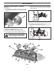
ASSEMBLY • ASSEMBLE FRONT WHEEL TO MOWER (See Fig. 3) • Turn steering wheel to the left as far as it will go and position mower on right side of tractor with deflector shield to the right. Using shoulder bolt, washer and locknut from parts bag, assemble front wheel to mower as shown. Tighten securely. 02965 FIG. 5 NOTE: Be sure mower side suspension arms (A) are pointing forward before sliding mower under tractor. • Slide mower under tractor until it is centered under tractor. FIG.
ASSEMBLY • FIRST INSTALL ANTI-SWAY BAR (S). • From right side of mower, insert anti-sway bar into hole in transmission bracket (T). C S T D FIG.10 A • FIG. 7 • • • Pivot bar towards you and insert other end of bar into hole in rear mower bracket (D). Move mower as needed to insert bar. Secure with washer and retainer spring as shown • ATTACH FRONT LINK (E) - Work from left side of tractor.
ASSEMBLY CHECK TIRE PRESSURE ✓CHECKLIST The tires on your tractor were overinflated at the factory for shipping purposes. Correct tire pressure is important for best cutting performance. • Reduce tire pressure to PSI shown on tires. BEFORE YOU OPERATE YOUR NEW TRACTOR, WE WISH TO ASSURE THAT YOU RECEIVE THE BEST PERFORMANCE AND SATISFACTION FROM THIS QUALITY PRODUCT. PLEASE REVIEW THE FOLLOWING CHECKLIST: ✓ All assembly instructions have been completed. ✓ No remaining loose parts in carton.
OPERATION These symbols may appear on your tractor or in literature supplied with the product. Learn and understand their meaning.
OPERATION KNOW YOUR TRACTOR READ THIS OWNER'S MANUAL AND SAFETY RULES BEFORE OPERATING YOUR TRACTOR Compare the illustrations with your tractor to familiarize yourself with the locations of various controls and adjustments. Save this manual for future reference. P H D E G B K F C J L A M Fig. 13 Our tractors conform to the applicable safety standards of the American National Standards Institute. (H) LIGHT SWITCH – Turns the headlights on and off.
OPERATION The operation of any tractor can result in foreign objects thrown into the eyes, which can result in severe eye damage. Always wear safety glasses or eye shields while operating your tractor or performing any adjustments or repairs. We recommend standard safety glasses or a wide vision safety mask worn over spectacles. HOW TO USE YOUR TRACTOR ENGINE • Move throttle control (D) between half and full speed (fast) position.
OPERATION • • J The average lawn should be cut to approximately 2-1/2" during the cool season and to over 3" during hot months. For healthier and better looking lawns, mow often and after moderate growth. For best cutting performance, grass over 6" in height should be mowed twice. Make the first cut relatively high; the second to desired height. TO ADJUST GAUGE WHEELS (See Fig.
OPERATION TO STOP MOWER BLADES TO OPERATE ON HILLS Disengage attachment clutch control. CAUTION: Do not drive up or down hills with slopes greater than 15° and do not drive across any slope. CAUTION: Do not operate the mower without either the entire grass catcher, on mowers so equipped, or the deflector shield (S) in place. (See Fig. 20) • • • S • • • Choose the slowest speed before starting up or down hills. Avoid stopping or changing speed on hills.
OPERATION TO START ENGINE (See Fig. X) SERVICE REMINDER/HOUR METER When starting the engine for the first time or if the engine has run out of fuel, it will take extra cranking time to move fuel from the tank to the engine. • Be sure freewheel control is in the transmission engaged position. • Sit on seat in operating position, depress brake pedal and set parking brake. • Move attachment clutch to “DISENGAGED” position. • Move throttle control to choke position.
OPERATION MOWING TIPS PURGE TRANSMISSION • CAUTION: Never engage or disengage freewheel lever while the engine is runing. • • To ensure proper operation and performance, it is recommended that the transmission be purged before operating tractor for the first time. This procedure will remove any trapped air inside the transmission which may have developed during shipping of your tractor.
MAINTENANCE MAINTENANCE SCHEDULE BEFORE EACH USE EVERY 8 HOURS EVERY 25 HOURS EVERY 50 HOURS EVERY 100 HOURS EVERY SEASON BEFORE STORAGE Check Brake Operation T R A C T 0 R Check Tire Pressure Check Operator Presence & ROS Systems Check for Loose Fasteners Check/Replace Mower Blades 3 Lubrication Chart Check Battery Level 4 Clean Battery and Terminals Clean Debris Off Steering Plate Check Transaxle Cooling 5 Check Mower Levelness Check V-Belts Check Engine Oil Level Change Engine Oil (with o
MAINTENANCE TRACTOR BLADE CARE For best results mower blades must be sharp. Replace worn, bent or damaged blades. Always observe safety rules when performing any maintenance. BRAKE OPERATION CAUTION: Use only a replacement blade approved by the manufacturer of your tractor. Using a blade not approved by the manufacturer of your tractor is hazardous, could damage your tractor and void your warranty.
MAINTENANCE V-BELTS OIL DRAIN VALVE Check V-belts for deterioration and wear after 100 hours of operation and replace if necessary. The belts are not adjustable. Replace belts if they begin to slip from wear. CLOSED AND LOCKED POSITION TRANSAXLE COOLING The transmission fan and cooling fins should be kept clean to assure proper cooling. Do not attempt to clean fan or transmission while engine is running or while the transmission is hot.
MAINTENANCE IN-LINE FUEL FILTER (See Fig. 26) DECK WASHOUT PORT (See Fig. 28) The fuel filter should be replaced once each season. If fuel filter becomes clogged, obstructing fuel flow to carburetor, replacement is required. • With engine cool, remove filter and plug fuel line sections. • Place new fuel filter in position in fuel line with arrow pointing towards carburetor. • Be sure there are no fuel line leaks and clamps are properly positioned. • Immediately wipe up any spilled gasoline.
SERVICE AND ADJUSTMENTS WARNING: TO AVOID SERIOUS INJURY, BEFORE PERFORMING ANY SERVICE OR ADJUSTMENTS: • Depress brake pedal fully and set parking brake. • Place attachment clutch in “DISENGAGED” position. • Turn ignition key to “STOP” and remove key. • Make sure the blades and all moving parts have completely stopped. • Disconnect spark plug wire from spark plug and place wire where it cannot come in contact with plug. TO REMOVE MOWER (See Fig. 29) • • • TO REPLACE MOWER BLADE DRIVE BELT (See Fig.
SERVICE AND ADJUSTMENTS TO LEVEL MOWER • If adjustment is necessary, see steps in Visual Adjustment instructions above. • Recheck measurements, adjust if necessary until both sides are equal. FRONT-TO-BACK ADJUSTMENT (See Figs. 33 & 34) IMPORTANT: Deck must be level side-to-side. To obtain the best cutting results, the mower blades should be adjusted so the front tip is 1/8" to 1/2" lower than the rear tip when the mower is in its highest position.
SERVICE AND ADJUSTMENTS TO CHECK BRAKE If tractor requires more than five (5) feet to stop at highest speed in highest gear on a level, dry concrete or paved surface, then brake must be serviced. You may also check brake by: • Park tractor on a level, dry concrete or paved surface, depress brake pedal all the way down and engage parking brake. • Disengage transmission by placing freewheel control in “transmission disengaged” position.
SERVICE AND ADJUSTMENTS REPLACING BATTERY (See Fig. 38) FRONT WHEEL TOE-IN/CAMBER Your new tractor front wheel toe-in and camber is set at the factory and is normal. The front wheel toe-in and camber are not adjustable. If damage has occurred to affect the factory set front wheel toe-in or camber, contact a qualified service center. WARNING: Do not short battery terminals by allowing a wrench or any other object to contact both terminals at the same time.
SERVICE AND ADJUSTMENTS ENGINE TO REPLACE HEADLIGHT BULB • • • • Raise hood. Pull bulb holder out of the hole in the backside of the grill. Replace bulb in holder and push bulb holder securely back into the hole in the backside of the grill. Close hood. TO ADJUST THROTTLE CONTROL CABLE The throttle control has been preset at the factory and adjustment should not be necessary. If adjustment is necessary, see engine manual.
STORAGE Immediately prepare your tractor for storage at the end of the season or if the tractor will not be used for 30 days or more. ENGINE FUEL SYSTEM IMPORTANT: IT IS IMPORTANT TO PREVENT GUM DEPOSITS FROM FORMING IN ESSENTIAL FUEL SYSTEM PARTS SUCH AS CARBURETOR, FUEL FILTER, FUEL HOSE, OR TANK DURING STORAGE. ALSO, EXPERIENCE INDICATES THAT ALCOHOL BLENDED FUELS (CALLED GASOHOL OR USING ETHANOL OR METHANOL) CAN ATTRACT MOISTURE WHICH LEADS TO SEPARATION AND FORMATION OF ACIDS DURING STORAGE.
TROUBLESHOOTING POINTS PROBLEM Will not start CAUSE 1. 2. 3. 4. 5. 6. 7. CORRECTION Out of fuel. Engine not “CHOKED” properly. Engine flooded. Bad spark plug. Dirty air filter. Dirty fuel filter. Water in fuel. 1. 2. 3. 4. 5. 6. 7. Fill fuel tank. See “TO START ENGINE” in Operation section. Wait several minutes before attempting to start. Replace spark plug. Clean/replace air filter. Replace fuel filter. Empty fuel tank and carburetor, refill tank with fresh gasoline and replace fuel filter. 8.
TROUBLESHOOTING POINTS PROBLEM CAUSE CORRECTION Engine continues to run when operator leaves seat with attachment clutch engaged 1. Faulty operator-safety presence control system. 1. Check wiring, switches and connections. If not corrected, contact an authorized service center/ department. Poor cut - uneven 1. 2. 3. 4. 5. Worn, bent or loose blade. Mower deck not level. Buildup of grass, leaves, trash under mower. Bent blade mandrel.
TRACTOR - MODEL NO. YTH2454 (96043009300), PRODUCT NO.
TRACTOR - MODEL NO. YTH2454 (96043009300), PRODUCT NO.
TRACTOR - MODEL NO. YTH2454 (96043009300), PRODUCT NO. 960 43 00-93 ELECTRICAL KEY NO. 1 2 8 16 21 22 24 25 26 27 28 29 30 33 34 40 41 42 43 46 50 55 71 79 90 91 99 100 102 105 PART NO.
TRACTOR - MODEL NO. YTH2454 (96043009300), PRODUCT NO.
TRACTOR - MODEL NO. YTH2454 (96043009300), PRODUCT NO. 960 43 00-93 CHASSIS KEY NO. PART NO.
TRACTOR - MODEL NO. YTH2454 (96043009300), PRODUCT NO.
TRACTOR - MODEL NO. YTH2454 (96043009300), PRODUCT NO. 960 43 00-93 DRIVE KEY NO. PART NO.
TRACTOR - MODEL NO. YTH2454 (96043009300), PRODUCT NO.
TRACTOR - MODEL NO. YTH2454 (96043009300), PRODUCT NO. 960 43 00-93 ENGINE KEY PART NO. NO.
TRACTOR - MODEL NO. YTH2454 (96043009300), PRODUCT NO.
TRACTOR - MODEL NO. YTH2454 (96043009300), PRODUCT NO. 960 43 00-93 STEERING ASSEMBLY KEY NO. PART NO.
TRACTOR - MODEL NO. YTH2454 (96043009300), PRODUCT NO.
TRACTOR - MODEL NO. YTH2454 (96043009300), PRODUCT NO. 960 43 00-93 MOWER DECK KEY NO. PART NO.
TRACTOR - MODEL NO. YTH2454 (96043009300), PRODUCT NO. 960 43 00-93 MOWER LIFT 87 87 7 90 98 89 3 10 88 97 2 91 97 91 87 89 lift-tex_3 89 87 KEY NO. PART NO. DESCRIPTION 2 3 7 10 87 88 89 532 42 20-27 532 19 52-31 532 41 15-55 532 19 63-14 532 19 42-09 532 41 07-10 819 19 19-12 Shaft Asm., Lift Lever Asm., Lift RH Grip, Lever Spring Torsion Pin Cotter 7/16 Bow Tie Lock Spring Lift Assist Washer Clear Zinc KEY NO. PART NO.
TRACTOR - MODEL NO. YTH2454 (96043009300), PRODUCT NO. 960 43 00-93 SEAT ASSEMBLY 1 8 8 8 7 7 8 41 40 10 21 6 37 6 37 2 44 43 21 3 seat-tex_6.5SL_3 KEY NO. PART NO. DESCRIPTION 1 2 3 6 7 8 10 21 532 42 40-68 532 18 01-66 532 14 06-75 873 80 06-00 532 12 41-81 532 17 18-77 532 19 69-77 532 17 18-52 Seat Bracket Pivot Fender Strap, Asm Fender Nut, Lock w/Ins. 3/8-16 unc Spring, Seat Cprsn Bolt 5/16-18 unc x 3/4 w/Sems Pan, Seat Bolt, Shoulder 5/16-18 KEY NO. PART NO.
TRACTOR - MODEL NO. YTH2454 (96043009300), PRODUCT NO. 960 43 00-93 DECALS 4 16 17 16 1 14 14 9 8 6 5 3 KEY NO. 1 3 4 5 6 8 9 14 PART NO. 532 41 16-58 532 17 05-63 532 42 38-29 532 17 84-55 532 40 88-42 532 19 87-85 532 14 50-05 532 43 19-87 DESCRIPTION Decal, Fender Warning Decal, Warning Decal, Hood Cust Resp Decal, Caution Decal, Eng. HP Decal, Mower Sch. Decal, Battery Dnge/Poi Decal, Panel Side WHEELS AND TIRES 1 2 11 3 4 7 10 5 6 9 8 KEY NO. 16 17 ---- PART NO.
SUGGESTED GUIDE FOR SIGHTING SLOPES FOR SAFE OPERATION ONLY RIDE UP AND DOWN HILL, NOT ACROSS HILL 15 DEGREES MAX. WARNING: To avoid serious injury, operate your tractor up and down the face of slopes, never across the face. Do not mow slopes greater than 15 degrees. Make turns gradually to prevent tipping or loss of control. Exercise extreme caution when changing direction on slopes. 1. Fold this page along dotted line indicated above. 2.
SERVICE NOTES 46
SERVICE NOTES 47
10.24.09 CL Printed in the U.S.A.