YTH2242 Owner's Manual / 96043010000 / 2009-10 532 43 14-93
SAFETY RULES Safe Operation Practices for Ride-On Mowers DANGER: THIS CUTTING MACHINE IS CAPABLE OF AMPUTATING HANDS AND FEET AND THROWING OBJECTS. FAILURE TO OBSERVE THE FOLLOWING SAFETY INSTRUCTIONS COULD RESULT IN SERIOUS INJURY OR DEATH. • • WARNING: In order to prevent accidental starting when setting up, transporting, adjusting or making repairs, always disconnect spark plug wire and place wire where it cannot contact spark plug.
SAFETY RULES Safe Operation Practices for Ride-On Mowers III. CHILDREN Tragic accidents can occur if the operator is not alert to the presence of children. Children are often attracted to the machine and the mowing activity. Never assume that children will remain where you last saw them. • Keep children out of the mowing area and in the watchful care of a responsible adult other than the operator. • Be alert and turn machine off if a child enters the area.
PRODUCT SPECIFICATIONS Gasoline Capacity and type: 2.50 Gallons Unleaded Regular Oil Type (API-SG-SL): SAE 30 (above 32°F) SAE 5W-30 (below 32°F) Oil Capacity: w/Filter: w/o Filter: Spark Plug: Champion QC12YC (Gap: .030") Ground Speed (MPH): Forward: Reverse: Charging System: 5 AMPS BATTERY 3 AMPS HEADLIGHTS Battery: AMP/HR: MIN. CCA: Case Size: Blade Bolt Torque: 45-55 Ft. Lbs. CUSTOMER RESPONSIBILITIES • • • 64 oz. 60 oz. Read and observe the safety rules.
UNASSEMBLED PARTS Slope Sheet Key (1) Oil Drain Tube (2) Keys ASSEMBLY Your new tractor has been assembled at the factory with the exception of those parts left unassembled for shipping purposes. TOOLS REQUIRED FOR ASSEMBLY A socket wrench set will make assembly easier. Standard wrench sizes are listed.
ASSEMBLY ✓CHECKLIST BEFORE YOU OPERATE YOUR NEW TRACTOR, WE WISH TO ASSURE THAT YOU RECEIVE THE BEST PERFORMANCE AND SATISFACTION FROM THIS QUALITY PRODUCT. PLEASE REVIEW THE FOLLOWING CHECKLIST: NOTE: You may now roll your tractor off the skid. Follow the instructions below to remove the tractor from the skid. WARNING: Before starting, read, understand and follow all instructions in the Operation section of this manual. Be sure tractor is in a well-ventilated area.
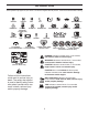
OPERATION These symbols may appear on your tractor or in literature supplied with the product. Learn and understand their meaning.
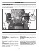
OPERATION KNOW YOUR TRACTOR READ THIS OWNER'S MANUAL AND SAFETY RULES BEFORE OPERATING YOUR TRACTOR Compare the illustrations with your tractor to familiarize yourself with the locations of various controls and adjustments. Save this manual for future reference. P H G E B D N F A M C K J L Fig. 3 Our tractors conform to the applicable safety standards of the American National Standards Institute. (H) LIGHT SWITCH - Turns the headlights on and off.
OPERATION The operation of any tractor can result in foreign objects thrown into the eyes, which can result in severe eye damage. Always wear safety glasses or eye shields while operating your tractor or performing any adjustments or repairs. We recommend standard safety glasses or a wide vision safety mask worn over spectacles. ENGINE • Move throttle control (D) between half and full speed (fast) position.
OPERATION TO USE CRUISE CONTROL (J) (See Fig. 7) TO ADJUST GAUGE WHEELS (See Fig. 9) The cruise control feature can be used for forward travel only. Gauge wheels are properly adjusted when they are slightly off the ground when mower is at the desired cutting height in operating position. Gauge wheels then keep the deck in proper position to help prevent scalping in most terrain conditions. NOTE: Adjust gauge wheels with tractor on a flat level surface.
OPERATION TO TRANSPORT (See Figs. 3 and 11) REVERSE OPERATION SYSTEM (ROS) When pushing or towing your tractor, be sure to disengage transmission by placing freewheel control in freewheeling position. Free wheel control is located at the rear drawbar of tractor. • Raise attachment lift to highest position with attachment lift control. • Pull freewheel control out and down into the slot and release so it is held in the disengaged position. • Do not push or tow tractor at more than two (2) MPH.
OPERATION TO START ENGINE (See Fig. 3) BEFORE STARTING THE ENGINE When starting the engine for the first time or if the engine has run out of fuel, it will take extra cranking time to move fuel from the tank to the engine. • Be sure freewheel control is in the transmission engaged position. • Sit on seat in operating position, depress brake pedal and set parking brake. • Move attachment clutch to “DISENGAGED” position.
OPERATION MOWING TIPS PURGE TRANSMISSION • CAUTION: Never engage or disengage freewheel lever while the engine is running. • • To ensure proper operation and performance, it is recommended that the transmission be purged before operating tractor for the first time. This procedure will remove any trapped air inside the transmission which may have developed during shipping of your tractor.
MAINTENANCE MAINTENANCE SCHEDULE BEFORE EACH USE EVERY 8 HOURS EVERY 25 HOURS EVERY 50 HOURS EVERY 100 HOURS EVERY SEASON BEFORE STORAGE Check Brake Operation T R A C T 0 R Check Tire Pressure Check Operator Presence & ROS Systems Check for Loose Fasteners Check/Replace Mower Blades 3 Lubrication Chart Check Battery Level 4 Clean Battery and Terminals Clean Debris Off Steering Plate Check Transaxle Cooling 5 Check Mower Levelness Check V-Belts Check Engine Oil Level Change Engine Oil (with o
MAINTENANCE TRACTOR BLADE CARE For best results mower blades must be kept sharp. Replace bent or damaged blades. Always observe safety rules when per form ing any maintenance. CAUTION: Use only a replacement blade approved by the manufacturer of your tractor. Using a blade not approved by the manufacturer of your tractor is hazardous, could damage your tractor and void your warranty.
MAINTENANCE V-BELTS OIL DRAIN VALVE Check V-belts for deterioration and wear after 100 hours of operation and replace if necessary. The belts are not adjustable. Replace belts if they begin to slip from wear. CLOSED AND LOCKED POSITION TRANSAXLE COOLING The transmission fan and cooling fins should be kept clean to assure proper cooling. Do not attempt to clean fan or transmission while engine is running or while the transmission is hot.
MAINTENANCE MUFFLER DECK WASHOUT PORT (See Fig. 30) Inspect and replace corroded muffler and spark arrester (if equipped) as it could create a fire hazard and/or damage. Your tractor’s deck is equipped with a washout port on its surface as part of its deck wash system. It should be utilized after each use. 1. Drive the tractor to a level, clear spot on your lawn, near enough to a water spigot for your garden hose to reach.
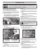
SERVICE AND ADJUSTMENTS WARNING: TO AVOID SERIOUS INJURY, BEFORE PERFORMING ANY SERVICE OR ADJUSTMENTS: • Depress brake pedal fully and set parking brake. • Place attachment clutch in “DISENGAGED” position. • Turn ignition key to “STOP” and remove key. • Make sure the blades and all moving parts have completely stopped. • Disconnect spark plug wire from spark plug and place wire where it cannot come in contact with plug. TO REMOVE MOWER (See Fig.
SERVICE AND ADJUSTMENTS • • • ATTACH MOWER SIDE SUSPENSION ARMS (A) TO CHASSIS - Position hole in arm over pin (B) on outside of tractor chassis and secure with retainer spring. Repeat on opposite side of tractor. Insert end of link (E) into hole in front mower bracket and secure with washer and retainer spring (J). E A J F H B • Fig.
SERVICE AND ADJUSTMENTS TO LEVEL MOWER • If adjustment is necessary, see step in Visual Adjustment instructions above. • Recheck measurements, adjust if necessary until both sides are equal. FRONT-TO-BACK ADJUSTMENT (See Figs. 28 & 29) IMPORTANT: Deck must be level side-to-side. To obtain the best cutting results, the mower blades should be adjusted so the front tip is 1/8" to 1/2" lower than the rear tip when the mower is in its highest position.
SERVICE AND ADJUSTMENTS TO REPLACE MOWER BLADE DRIVE BELT (See Fig. 30) TO REPLACE MOTION DRIVE BELT (See Fig. 31) The mower blade drive belt may be replaced without tools. Park the tractor on level surface. Engage parking brake. Park the tractor on level surface. Engage parking brake. For assistance, there is a belt installation guide decal on bottom side of left footrest. BELT REMOVAL • Remove mower from tractor (See “TO REMOVE MOWER” in this section of manual).
SERVICE AND ADJUSTMENTS TO REMOVE WHEEL (See Fig. 32) TO REMOVE CABLES, REVERSE ORDER • BLACK cable first from chassis and then from the fully charged battery. • RED cable last from both batteries. • • Block up axle securely. Remove axle cover, retaining ring and washers to allow wheel removal (rear wheel contains a square key - Do not lose). • Repair tire and reassemble. • On rear wheels only: align grooves in rear wheel hub and axle. Insert square key.
SERVICE AND ADJUSTMENTS TRANSMISSION TO REPLACE HEADLIGHT BULB • • • • Raise hood. Pull bulb holder out of the hole in the backside of the grill. Replace bulb in holder and push bulb holder securely back into the hole in the backside of the grill. Close hood. REMOVAL/REPLACEMENT Should your transmission require removal for service or replacement, it should be purged after reinstallation and before operating the tractor. See “PURGE TRANSMISSION” in the Operation section of this manual.
STORAGE ENGINE Immediately prepare your tractor for storage at the end of the season or if the tractor will not be used for 30 days or more. FUEL SYSTEM IMPORTANT: IT IS IMPORTANT TO PREVENT GUM DEPOSITS FROM FORMING IN ESSENTIAL FUEL SYSTEM PARTS SUCH AS CARBURETOR, FUEL FILTER, FUEL HOSE, OR TANK DURING STORAGE. ALSO, EXPERIENCE INDICATES THAT ALCOHOL BLENDED FUELS (CALLED GASOHOL OR USING ETHANOL OR METHANOL) CAN ATTRACT MOISTURE WHICH LEADS TO SEPARATION AND FORMATION OF ACIDS DURING STORAGE.
TROUBLESHOOTING PROBLEM Will not start CAUSE 1. 2. 3. 4. 5. 6. 7. CORRECTION Out of fuel. Engine not “CHOKED” properly. Engine flooded. Bad spark plug. Dirty air filter. Dirty fuel filter. Water in fuel. 1. 2. 3. 4. 5. 6. 7. Fill fuel tank. See “TO START ENGINE” in Operation section. Wait several minutes before attempting to start. Replace spark plug. Clean/replace air filter. Replace fuel filter. Empty fuel tank and carburetor, refill tank with fresh gasoline and replace fuel filter. 8.
TROUBLESHOOTING PROBLEM CAUSE CORRECTION Engine continues to run when operator leaves seat with attachment clutch engaged 1. Faulty operator-safety presence control system. 1. Check wiring, switches and connections. If not corrected, contact an authorized service center/ department. Poor cut - uneven 1. 2. 3. 4. 5. Worn, bent or loose blade. Mower deck not level. Buildup of grass, leaves, trash under mower. Bent blade mandrel.
TRACTOR - - MODEL NUMBER YTH2242 (96043010000), PRODUCT NO. 960 43 01-00 SCHEMATIC SCH11 BATTERY RED SOLENOID A M FUSE AMMETER (OPTIONAL) BLACK WHITE S B G STARTER RED WHITE M A1 L A2 ATTACHMENT CLUTCH (CLUTCH OFF) BLACK CLUTCH/BRAKE (PEDAL UP) GRAY REVERSE SWITCH (NOT IN REVERSE) BLACK BLACK BLACK 2 BLACK 3 BLACK BLACK SEAT SWITCH (NOT OCCUPIED) BLACK BLACK 1 6 GRAY SHORTING CONNECTOR CHASSIS HARNESS IGNITION UNIT (OPTIONAL) SPARK PLUGS GAP (2 PLUGS ON TWIN CYL.
TRACTOR - - MODEL NUMBER YTH2242 (96043010000), PRODUCT NO.
TRACTOR - - MODEL NUMBER YTH2242 (96043010000), PRODUCT NO. 960 43 01-00 ELECTRICAL KEY NO. 1 2 8 16 21 22 25 26 27 28 29 30 33 34 40 41 42 43 46 55 71 79 87 90 102 105 PART NO.
TRACTOR - - MODEL NUMBER YTH2242 (96043010000), PRODUCT NO.
TRACTOR - - MODEL NUMBER YTH2242 (96043010000), PRODUCT NO. 960 43 01-00 CHASSIS KEY NO. PART NO.
TRACTOR - - MODEL NUMBER YTH2242 (96043010000), PRODUCT NO.
TRACTOR - - MODEL NUMBER YTH2242 (96043010000), PRODUCT NO. 960 43 01-00 DRIVE KEY NO. PART NO.
TRACTOR - - MODEL NUMBER YTH2242 (96043010000), PRODUCT NO.
TRACTOR - - MODEL NUMBER YTH2242 (96043010000), PRODUCT NO. 960 43 01-00 ENGINE KEY NO. PART NO.
TRACTOR - - MODEL NUMBER YTH2242 (96043010000), PRODUCT NO.
TRACTOR - - MODEL NUMBER YTH2242 (96043010000), PRODUCT NO. 960 43 01-00 STEERING ASSEMBLY KEY NO. 1 2 4 5 6 7 8 9 13 14 15 16 19 21 22 26 28 35 45 51 53 57 58 59 60 61 62 63 64 66 67 68 69 70 PART NO.
TRACTOR - - MODEL NUMBER YTH2242 (96043010000), PRODUCT NO.
TRACTOR - - MODEL NUMBER YTH2242 (96043010000), PRODUCT NO. 960 43 01-00 MOWER DECK KEY PART NO. NO.
TRACTOR - - MODEL NUMBER YTH2242 (96043010000), PRODUCT NO. 960 43 01-00 MOWER LIFT 87 7 87 90 98 89 10 3 97 100 2 88 97 91 101* 89 lift-tex_22 KEY NO. 2 3 7 10 87 88 89 90 91 87 *Key 91 may be substituted for Key 101 KEY NO. 97 98 100 101 PART NO. DESCRIPTION 532 42 20-27 Shaft Asm., Lift 532 19 52-31 Lever Asm.
TRACTOR - - MODEL NUMBER YTH2242 (96043010000), PRODUCT NO. 960 43 01-00 SEAT ASSEMBLY 1 8 8 8 7 7 8 41 40 10 21 6 37 6 37 2 44 43 21 3 seat-tex_6.5SL_3 KEY NO. 1 2 3 6 7 8 10 21 PART NO. 532 42 40-68 532 18 01-66 532 14 06-75 873 80 06-00 532 12 41-81 532 17 18-77 532 19 69-77 532 17 18-52 KEY NO. DESCRIPTION 37 40 41 43 44 Seat Bracket Pivot Fender Strap, Asm Fender Nut, Lock w/Ins. 3/8-16 unc Spring, Seat Cprsn Bolt 5/16-18 unc x 3/4 w/Sems Pan, Seat Bolt, Shoulder 5/16-18 PART NO.
TRACTOR - - MODEL NUMBER YTH2242 (96043010000), PRODUCT NO. 960 43 01-00 DECALS 2 5 6 2 9 3 1 7 4 12 KEY NO. 1 2 3 4 5 6 7 PART NO. KEY NO. DESCRIPTION 532 41 16-58 532 42 20-12 532 43 20-19 532 40 88-40 532 42 38-29 532 43 20-17 532 17 05-63 9 12 ---- Decal, Fender Warning Decal, Hood Decal, Hood Panel SD Decal, Engine H.P. Decal, Customer Respons. Decal, Replacement Decal, Mower Warn. Keep Hands Away WHEELS AND TIRES KEY NO. 1 2 3 4 5 6 7 8 9 10 11 -- 1 2 11 3 4 7 10 5 6 9 8 PART NO.
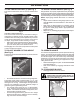
SUGGESTED GUIDE FOR SIGHTING SLOPES FOR SAFE OPERATION ONLY RIDE UP AND DOWN HILL, NOT ACROSS HILL 15 DEGREES MAX. WARNING: To avoid serious injury, operate your tractor up and down the face of slopes, never across the face. Do not mow slopes greater than 15 degrees. Make turns gradually to prevent tipping or loss of control. Exercise extreme caution when changing direction on slopes. 1. Fold this page along dotted line indicated above. 2.
10.24.09 SR Printed in the U.S.A.
10.23.09 CL Printed in the U.S.A.