
Product Manual


6
ASSEMBLY
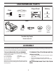
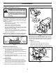
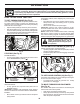
CONNECT BATTERY (See Fig. 1)
NOTE: If this battery is put into service after month and
year indicated on label (label is located between terminals)
charge battery for minimum of one hour at 6-10 amps. (See
“BATTERY” in the Maintenance section of this manual for
charging instructions.)
• Determine battery location. Battery location will be
under the seat or the hood.
• Lift seat pan or hood to raised position.
• Remove two terminal caps and discard.
• First connect RED battery cable to positive (+) terminal
with bolt and nut as shown. Tighten securely. Slide
terminal cover over terminal.
• Connect BLACK grounding cable to negative (-)
ter mi nal with remaining bolt and nut. Tighten se cure ly.
• Lower seat pan or hood.
NOTE: For battery installation see “REPLACING BATTERY”
in the Service and Adjustments section in this manual.
Fig. 1
02605
NUT
POSITIVE
(RED)
CABLE
NEGATIVE
(BLACK)
CABLE
BOLT
TERMINAL
COVER
LABEL
TERMINAL
CAP
WARNING: Do not short battery ter mi nals
by allowing a wrench or any other object
to contact both terminals at the same
time. Before connecting battery, remove
metal bracelets, wristwatch bands, rings,
etc. Positive terminal must be connected
first to prevent sparking from ac ci den tal
grounding.
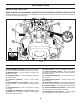
Fig. 2
INSTALL SEAT (See Fig. 2)
Adjust seat before tightening adjustment knob.
• Pivot seat upward and remove from the unit. Remove
the cardboard and foam packing and discard.
• Retrieve the knob, cup washer, three bolts and washers
from the bag of parts.
• Pivot seat and pan forward and assemble three bolts
and washers. Tighten securely.
• As sem ble adjustment knob and cup washer loosely.
Do not tighten.
TO ADJUST SEAT
• Lower seat into operating position and sit in seat.
• Slide seat until a comfortable position is reached which
allows you to press clutch/brake pedal all the way down.
• Get off seat without moving its ad just ed position.
• Raise seat and tighten adjustment knob securely.
SEAT
BOLT
BOLT
BOLT
WASHER
WASHER
WASHER
ADJUSTMENT KNOB
CUP
WASHER
SEAT PAN
6000
Fig. 3
VERTICAL SEAT ADJUSTMENT (See Fig. 3)
Seat pan comes in the upper position from the factory and
can be moved to the lower position for shorter operators.
TO ADJUST
• Remove nuts and bolts.
• Relocate seat pan assembly to lower position.
• Reinstall bolts and nuts, tighten to 15-20 ft. lbs.
• Refer to "TO ADJUST SEAT" for final seat adjustment.
NUTS
UPPER
POSITION
LOWER
POSITION
BOLT
BOLT