KT610-KT620, KT715-KT745 Service Manual IMPORTANT: Read all safety precautions and instructions carefully before operating equipment. Refer to operating instruction of equipment that this engine powers. Ensure engine is stopped and level before performing any maintenance or service.
Safety SAFETY PRECAUTIONS WARNING: A hazard that could result in death, serious injury, or substantial property damage. CAUTION: A hazard that could result in minor personal injury or property damage. NOTE: is used to notify people of important installation, operation, or maintenance information. WARNING Explosive Fuel can cause fires and severe burns. Do not fill fuel tank while engine is hot or running. Gasoline is extremely flammable and its vapors can explode if ignited.
Maintenance MAINTENANCE INSTRUCTIONS WARNING Accidental Starts can cause severe injury or death. Disconnect and ground spark plug lead(s) before servicing. Before working on engine or equipment, disable engine as follows: 1) Disconnect spark plug lead(s). 2) Disconnect negative (–) battery cable from battery.
Maintenance OIL RECOMMENDATIONS We recommend use of Kohler oils for best performance. Other high-quality detergent oils (including synthetic) of API (American Petroleum Institute) service class SJ or higher are acceptable. Select viscosity based on air temperature at time of operation as shown in table below. 10W-30 SAE 30 5W-30 °F -20 °C -30 0 -20 20 -10 32 40 0 50 10 80 60 20 STORAGE If engine will be out of service for 2 months or more follow procedure below. 1.
Specifications Engine Dimensions with Low Profile or High Performance Air Cleaner-Flywheel Side A M C B D K H E J F L I G A 423.0 mm (16.65 in.) B 136.7 mm (5.38 in.) C 89.6 mm (3.53 in.) D 50.1 mm (1.97 in.) E Oil Fill and Dipstick (Yellow) F Fuel Line Connection Point G Mounting Hole "A" H 136.9 mm (5.39 in.) I 141.5 mm (5.57 in.) J 89.7 mm (3.53 in.) K 307.9 mm (12.12 in.) L 7.2 mm (0.28) Center of Gravity M 45.5 mm (1.79 in.) Center of Gravity 32 690 03 Rev.
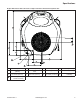
Specifications Engine Dimensions with Low Profile or High Performance Air Cleaner-Oil Filter Side K A I B J L C H M G D 6 E F A 355.1 mm (13.98 in.) Low Profile Air Cleaner Removal B 329.1 mm (12.96 in.) Top of Low Profile Air Cleaner C 159.4 mm (6.28 in.) Center of Gravity D Engine Mounting Surface E 80.3 mm (3.16 in.) Oil Filter F Mounting Hole "A" G 51.2 mm (2.02 in.) Oil Filter H 134.0 mm (5.28 in.) Spark Plug Center Line L 392.1 mm (15.44 in.
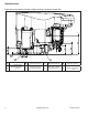
Specifications Engine Dimensions with Low Profile or High Performance Air Cleaner-Engine Mounting Surface (PTO End) A B B C D E F G G I H U T K J S L M R O P L N L Q A 334.3 mm (13.16 in.) B 72.8 mm (2.87 in.) C 94.3 mm (3.71 in.) D 48.1 mm (1.89 in.) E Evap Connection Point F 4 X 5/16-18 UNC-2B in. 16.5 mm (0.649 in.) Deep No Studs G 30° H 50.0 mm (1.97 in.) Exhaust Port #2 I 268.3 mm (10.56 in.) J 104.0 mm (4.10 in.) K 242.1 mm (9.53 in.) L 89.8 mm (3.54 in.) M 18.
Specifications Engine Dimensions with Low Profile or High Performance Air Cleaner-Starter Side H F A B D C 8 G E A 55.8 mm (2.20 in.) Starter Stud B 13.0 mm (0.51 in.) C Mounting Hole "A" D 40.8 mm (1.61 in.) E Engine Mounting Surface F 72.0 mm (2.83 in.) Exhaust Port #2 G 92.0 mm (3.62 in.) Exhaust Port #1 H 154.0 mm (6.06 in.) Spark Plug Center Line KohlerEngines.com 32 690 03 Rev.
Specifications Engine Dimensions with Low Profile or High Performance Air Cleaner-Valve Cover Side A F E B D C A 87.6 mm (3.45 in.) B Engine Mounting Surface E Mounting Hole "A" F 39.8 mm (1.57 in.) 32 690 03 Rev. I C 152.9 mm (6.02 in.) KohlerEngines.com D 4.4 mm (0.17 in.
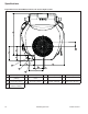
Specifications Engine Dimensions with PRO Performance Air Cleaner-Flywheel Side A M C B D G E L J F H K I A 424.7 mm (16.72 in.) B 136.7 mm (5.38 in.) C 89.6 mm (3.53 in.) D 50.1 mm (1.97 in.) E Oil Fill and Dipstick (Yellow) F Fuel Line Connection Point G 136.9 mm (5.39 in.) H Mounting Hole "A" I 141.5 mm (5.57 in.) J 89.7 mm (3.53 in.) K 9.7 mm (0.38 in.) Center of Gravity L 307.9 mm (12.12 in.) M 47.0 mm (1.85 in.) Center of Gravity 10 KohlerEngines.
Specifications Engine Dimensions with PRO Performance Air Cleaner-Oil Filter Side M L A K J B C D I H E F G A 458.7 mm (18.06 in.) Air Cleaner Removal B 398.7 mm (15.70 in.) Top of Air Cleaner C 265.2 mm (10.44 in.) Evap Connection Point D 166.5 mm (6.56 in.) Center of Gravity E Engine Mounting Surface F 80.3 mm (3.16 in.) Oil Filter G Mounting Hole "A" H 51.2 mm (2.02 in.) Oil Filter J 340.9 mm (13.42 in.) K 380.7 mm (14.99 in.) L Optional Fixed Guard I 134.0 mm (5.28 in.
Specifications Engine Dimensions with PRO Performance Air Cleaner-Engine Mounting Surface (PTO End) A B C B D E E F S R H G Q I J L O P K N N M A 334.3 mm (13.16 in.) B 72.8 mm (2.87 in.) C 94.3 mm (3.71 in.) D 4 X 5/16-18 UNC-2B in. 16.5 mm (0.649 in.) Deep No Studs E 30° F 50.0 mm (1.97 in.) Exhaust Port #2 G 242.1 mm (9.53 in.) H 104.0 mm (4.10 in.) I 89.8 mm (3.54 in.) J 18.0 mm (0.71 in.) Oil Filter Removal K 116.8 mm (4.60 in.) L Mounting Hole "A" M 248.1 mm (9.
Specifications Engine Dimensions with PRO Performance Air Cleaner-Starter Side H F A B G D C E A 55.8 mm (2.20 in.) Starter Stud B 13.0 mm (0.51 in.) C Mounting Hole "A" D 40.8 mm (1.61 in.) E Engine Mounting Surface F 72.0 mm (2.83 in.) Exhaust Port #2 G 92.0 mm (3.62 in.) Exhaust Port #1 H 154.0 mm (6.06 in.) Spark Plug Center Line 32 690 03 Rev. I KohlerEngines.
Specifications Engine Dimensions with PRO Performance Air Cleaner-Valve Cover Side A F E B D C A 87.6 mm (3.45 in.) B Engine Mounting Surface E Mounting Hole "A" F 39.8 mm (1.57 in.) 14 C 152.9 mm (6.02 in.) KohlerEngines.com D 4.4 mm (0.17 in.) 32 690 03 Rev.
Specifications ENGINE IDENTIFICATION NUMBERS Kohler engine identification numbers (model, specification and serial) should be referenced for efficient repair, ordering correct parts, and engine replacement. Model . . . . . . . . . . . . . . . . . . . . . KT715 7000 Series Engine Numerical Designation Specification . . . . . . . . . . . . . . . KT715-0001 Serial . . . . . . . . . . . . . . . . . . . . .
Specifications TORQUE SPECIFICATIONS3,5 KT610 KT620 KT715 Carburetor Mounting Nut KT730 KT735 6.2 N·m (55 in. lb.) into new hole 4.0 N·m (35 in. lb.) into used hole 1.3 N·m (11.5 in. lb.) 13.6 N·m (10 ft. lb.) Cylinder Head Head Bolt Fastener (torque in 2 increments) Rocker Arm Stud first to 22.6 N·m (200 in. lb.) finally to 41.8 N·m (370 in. lb.) 11.3 N·m (100 in. lb.) Flywheel Retaining Screw 74.5 N·m (55 ft. lb.) Fuel Pump Screw 2.8 N·m (25 in. lb.) Governor Lever Nut 6.8 N·m (60 in. lb.
Specifications KT610 KT620 TORQUE SPECIFICATIONS3,5 KT715 Solenoid (Starter) Mounting Hardware Nut, Positive (+) Brush Lead KT725 KT730 KT735 10.7 N·m (95 in. lb.) into new holes 7.3 N·m (65 in. lb.) into used holes Starter Assembly Thru Bolt Inertia Drive Solenoid Shift Mounting Screw Brush Holder Mounting Screw 4.5-5.7 N·m (40-50 in. lb.) 5.6-9.0 N·m (49-79 in. lb.) 23.8 N·m (211 in. lb.) 2.5-3.3 N·m (22-29 in. lb.) Stator Mounting Screw 8.8 N·m (78 in. lb.) Valve Cover Fastener 9.
Specifications CLEARANCE SPECIFICATIONS3 Crankshaft End Play (free) Bore (in crankcase) New Max. Wear Limit Bore (in oil pan) New Crankshaft Bore (in oil pan)-to-Crankshaft Running Clearance New Flywheel End Main Bearing Journal O.D. - New O.D. - Max. Wear Limit Max. Taper Max. Out-of-Round Oil Pan End Main Bearing Journal O.D. - New O.D. - Max. Wear Limit Max. Taper Max. Out-of-Round Connecting Rod Journal O.D. - New O.D. - Max. Wear Limit Max. Taper Max. Out-of-Round T.I.R.
Specifications KT610 KT620 CLEARANCE SPECIFICATIONS3 Ignition Spark Plug Gap Module Air Gap 3 7 KT725 KT730 KT735 KT740 KT745 0.76 mm (0.030 in.) 0.203/0.305 mm (0.008/0.012 in.) Piston, Piston Rings, and Piston Pin Piston-to-Piston Pin Running Clearance Pin Bore I.D. New Max. Wear Limit Pin O.D. New Max.
Specifications GENERAL TORQUE VALUES English Fastener Torque Recommendations for Standard Applications Bolts, Screws, Nuts and Fasteners Assembled Into Cast Iron or Steel Grade 2 or 5 Fasteners Into Aluminum Size Grade 2 Tightening Torque: N·m (in. lb.) ± 20% 8-32 2.3 (20) 10-24 3.6 (32) 10-32 3.6 (32) 1/4-20 7.9 (70) 1/4-28 9.6 (85) 5/16-18 17.0 (150) 5/16-24 18.7 (165) 3/8-16 29.4 (260) 3/8-24 33.9 (300) Grade 5 Grade 8 2.8 (25) 4.5 (40) 4.5 (40) 13.0 (115) 15.8 (140) 28.3 (250) 30.
Tools and Aids Certain quality tools are designed to help you perform specific disassembly, repair, and reassembly procedures. By using these tools, you can properly service engines easier, faster, and safer! In addition, you’ll increase your service capabilities and customer satisfaction by decreasing engine downtime. Here is a list of tools and their source. SEPARATE TOOL SUPPLIERS Kohler Tools Contact your local Kohler source of supply. SE Tools 415 Howard St.
Tools and Aids TOOLS Description Hose Removal Tool, Dual Size/End (also available in EFI Service Kit) Used to properly remove fuel hose from engine components. Hydraulic Valve Lifter Tool For removing and installing hydraulic lifters. Ignition System Tester For testing output on all systems, including CD. Inductive Tachometer (Digital) For checking operating speed (RPM) of an engine. Offset Wrench (K and M Series) For removing and reinstalling cylinder barrel retaining nuts.
Tools and Aids FLYWHEEL HOLDING TOOL ROCKER ARM/CRANKSHAFT TOOL A flywheel holding tool can be made out of an old junk flywheel ring gear and used in place of a strap wrench. 1. Using an abrasive cut-off wheel, cut out a six tooth segment of ring gear as shown. 2. Grind off any burrs or sharp edges. 3. Invert segment and place it between ignition bosses on crankcase so tool teeth engage flywheel ring gear teeth.
Troubleshooting TROUBLESHOOTING GUIDE When troubles occur, be sure to check simple causes which, at first, may seem too obvious to be considered. For example, a starting problem could be caused by an empty fuel tank. Some general common causes of engine troubles are listed below and vary by engine specification. Use these to locate causing factors. Engine Cranks But Will Not Start ● Battery connected backwards. ● Blown fuse. ● Carburetor solenoid malfunction. ● Choke not closing.
Troubleshooting Engine Loses Power ● Dirty air cleaner element. ● Engine overheated. ● Excessive engine load. ● Restricted exhaust. ● Faulty spark plug(s). ● High crankcase oil level. ● Incorrect governor setting. ● Low battery. ● Low compression. ● Low crankcase oil level. ● Quality of fuel (dirt, water, stale, mixture). Engine Uses Excessive Amount of Oil ● Loose or improperly torqued fasteners. ● Blown head gasket/overheated. ● Breather reed broken. ● Clogged, broken, or inoperative crankcase breather.
Troubleshooting CRANKCASE VACUUM TEST WARNING WARNING Carbon Monoxide can cause severe nausea, fainting or death. Avoid inhaling exhaust fumes. Engine exhaust gases contain poisonous carbon monoxide. Carbon monoxide is odorless, colorless, and can cause death if inhaled. Rotating Parts can cause severe injury. Stay away while engine is in operation. Keep hands, feet, hair, and clothing away from all moving parts to prevent injury. Never operate engine with covers, shrouds, or guards removed.
Troubleshooting COMPRESSION TEST For Command Twins: A compression test is best performed on a warm engine. Clean any dirt or debris away from base of spark plug(s) before removing them. Be sure choke is off, and throttle is wide open during test. Compression should be at least 160 psi and should not vary more than 15% between cylinders. All other models: These engines are equipped with an automatic compression release (ACR) mechanism.
Air Cleaner/Intake AIR CLEANER These systems are CARB/EPA certified and components should not be altered or modified in any way. Air Cleaner Components A G B B D H C C E Precleaner (if equipped) 1. Remove precleaner from paper element. 2. Replace or wash precleaner in warm water with detergent. Rinse and allow to air dry. 3. Lightly oil precleaner with new engine oil; squeeze out excess oil. 4. Reinstall precleaner over paper element. E F F Paper Element 1.
Air Cleaner/Intake If air cleaner base requires removal, proceed as follows: 1. Remove mounting screws for fuel pump (if equipped), and blower housing. 2. Raise or remove blower housing for access to air cleaner base. 3. Remove air cleaner components from base. 4. Remove nuts securing air cleaner base onto mounting studs. 5. Disconnect ground lead and fuel shut-off solenoid lead (if equipped). 6. If equipped with eChoke™, disconnect connecter from stepper motor. 7.
Fuel System Typical carbureted fuel system and related components include: ● Fuel tank. ● Fuel lines. ● In-line fuel filter. ● Fuel pump. ● Carburetor. Fuel from tank is moved through in-line filter and fuel lines by fuel pump. Fuel then enters carburetor float bowl and is drawn into carburetor body and mixed with air. This fuel-air mixture is then burned in engine combustion chamber. FUEL RECOMMENDATIONS Refer to Maintenance. FUEL LINE Low permeation fuel line must be installed on carbureted Kohler Co.
Fuel System CARBURETOR Walbro One-Barrel Carburetor Components B WARNING Explosive Fuel can cause fires and severe burns. Do not fill fuel tank while engine is hot or running. G Gasoline is extremely flammable and its vapors can explode if ignited. Store gasoline only in approved containers, in well ventilated, unoccupied buildings, away from sparks or flames. Spilled fuel could ignite if it comes in contact with hot parts or sparks from ignition. Never use gasoline as a cleaning agent.
Fuel System Troubleshooting-Carburetor Related Causes Condition Engine runs rich (indicated by black, sooty exhaust smoke, misfiring, loss of speed and power, governor hunting, or excessive throttle opening). Engine runs lean (indicated by misfiring, loss of speed and power, governor hunting, or excessive throttle opening). Fuel leaks from carburetor. Possible Cause Clogged air cleaner. Choke partially closed during operation. Float level is set too high. Conclusion Clean or replace air cleaner.
Fuel System Carburetor Adjustments NOTE: Carburetor adjustments should be made only after engine has warmed up. Carburetor is designed to deliver correct fuel-to-air mixture to engine under all operating conditions. Main fuel jet is calibrated at factory and is not adjustable. Idle fuel adjusting needles are also set at factory and are not adjustable. Idle Speed (RPM) Adjustment 1. Hold governor lever away from carburetor so throttle lever is against idle speed (RPM) adjustment screw of carburetor.
Fuel System For Keihin Carburetors Only To install choke repair kit go to step 10, otherwise go to step 21. 10. Remove and discard plastic cap from top of choke lever/shaft assembly. 11. Note position of spring legs and choke plate for correct reassembly later. 12. Remove two screws attaching choke plate to choke shaft. Pull shaft out of carburetor body and discard removed parts. 13. Use a screw extractor (easy out) and remove original choke shaft bushing with old choke lever from carburetor housing.
Fuel System Smart-Choke™ An air vane deflector assembly that operates by air from cooling fan opens choke partially when engine is running. When engine is cold, a spring on air vane deflector assembly, in conjunction with a bimetallic spring, holds choke closed for starting. A bimetallic spring reacts to heat generated by electrical resistance as engine is running and opens choke plate position. When engine is warm, bimetallic spring holds choke completely open, while engine is running.
Fuel System Troubleshooting Smart-Choke™ Related Causes Condition Engine starts hard, runs rough, or stalls at idle speed. Possible Cause Choke not closing. Engine runs rich (indicated by black, sooty exhaust smoke, misfiring, loss of speed and power, governor hunting, or excessive throttle opening). Choke partially closed during operation. Choke not opening.
Fuel System 11. With engine running, check voltage at bimetallic spring choke bracket assembly. Using a DVOM, attach black lead of meter to ground screw on assembly bracket, and red lead of meter to red wire w/black tracer. 12. Select DC VOLTS on your meter. You should see a minimum of 12 volts DC. If no voltage is present, test for voltage at oil pressure switch. If voltage is present at power in terminal but not at power out terminal when engine is running, pressure switch is potentially faulty.
Fuel System Adjustable Thermostat G A D D E E C B F F A Spring Tab Must be Located in Lever Slot E Low Position of Adjustment Range B Models KT725, KT735 C Models KT740, KT745 F This Edge of Metallic Ground Strap Must Fall Within Adjustment Range G Lever Slot D High Position of Adjustment Range Adjustable Thermostat Reset NOTE: Do not remove or loosen thermostat screws. Position is set at factory. NOTE: Thermostat temperature must be at room temperature before testing.
Fuel System Dual Position Thermostat B A F E D C C D A E CDI Ignition Module (Top View) Spring Tab Must be Located in Lever Slot B MDI Ignition Module (Top View) F Lever Slot C CDI Position D MDI Position Dual Position Thermostat Installation NOTE: Thermostat temperature must be at room temperature before testing. 1. Determine operating position of thermostat. Thermostat position is determined by ignition system: Capacitive Discharge Ignition (CDI) or Magnetic Discharge Ignition (MDI).
Fuel System Starting and Engine Equipped with Smart-Choke™ NOTE: Do not crank engine continuously for more than 10 seconds at a time. If engine does not start, allow a 60 second cool down period between starting attempts. Failure to follow these guidelines can burn out starter motor. NOTE: If engine develops sufficient speed to disengage starter but does not keep running (a false start), engine rotation must be allowed to come to a complete stop before attempting to restart engine.
Fuel System Electronic Choke (eChoke™) eChoke™ is an integrated control system that checks ambient and engine temperatures and monitors engine speed. This system is integrated through wiring to a master ignition/control module. Extended cranking (beyond 10 seconds) is not necessary, nor will it improve engine starting. Calculations and unique software routines developed specifically for this Kohler engine operate a carburetor choke lever through an assembly (bracket, linkage) to control a stepper motor.
Fuel System eChoke™ System Standard Checks NOTE: Procedures and troubleshooting may be easier to perform with engine cover removed. Refer to Disassembly/Inspection and Service and Reassembly procedure. Use these procedures and guides to troubleshoot this system and its components. Perform a system reset prior to troubleshooting to verify problem still exists. Start with key switch in OFF position, operate through On-OffOn sequence and restart engine.
Fuel System Operational Tests Test Step Number Operation 1 Power Cycle 1A Apply Power Description of Operation MIL Lamp Status Remove and reconnect engine connector. Turn key from OFF to ON. ON What is happening at eChoke™ Choke system will cycle to complete open and then complete close. ON OFF ON DELAY System activated, temperature read, waiting for engine to crank & start. Other MIL lamp sequence indicates failure mode 2B. Looking for starting engine speed.
Fuel System Failure Modes 1B 44 Failure to Start ON Pause at RUN and attempt to CRANK engine. Limit cranking time to about 5 seconds. For first 4 failed crank attempts, choke will reposition at each attempt. After four (4) attempts, key OFF and make one final attempt to start. Check other components (spark plug, ignition, carburetor, fuel solenoid). 2B Faulty temperature sensor.
Fuel System Troubleshooting eChoke™ Related Causes Condition Engine starts hard, runs rough, or stalls at idle speed. Engine runs rich (indicated by black, sooty exhaust smoke, misfiring, loss of speed and power, governor hunting, or excessive throttle opening). Engine runs lean (indicated by misfiring, loss of speed and power, governor hunting, or excessive throttle opening). 32 690 03 Rev. I Possible Cause Choke not closing/moving a. Incorrect set up of stepper motor/link/bracket to carburetor. b.
Fuel System Starting an Engine Equipped with eChoke™ NOTE: Do not crank engine continuously for more than 10 seconds at a time. If engine does not start, allow a 60 second cool down period between starting attempts. Failure to follow these guidelines can burn out starter motor. NOTE: If engine develops sufficient speed to disengage starter but does not keep running (a false start), engine rotation must be allowed to come to a complete stop before attempting to restart engine.
Fuel System Governor/Throttle Control Connections A H C E I I J H F K M A E E B G D C F B C A Left Side Pull B Cable Clamp C Speed Control Lever D Speed Setting Lever E Choke Lever F Right Side Pull G Contact Point H Choke Control Cable I Throttle Control Cable J Dual Control High Speed Lever Stop Screw (Do Not Remove) K High Speed Adjusting Screw L Choke Linkage M High Speed Control Lever 32 690 03 Rev. I KohlerEngines.
Fuel System UNITIZED THROTTLE AND CHOKE CONTROL Some engines are equipped with a unitized throttle and choke control. This assembly controls choke and engine speed with a single lever. Engines with a unitized throttle and choke control will have either a left side pull or a right side pull. Throttle Cable Adjustment NOTE: Choke is placed ON by moving throttle control slightly past fast position.
Governor System GOVERNOR Governed speed setting is determined by position of throttle control. It can be variable or constant, depending on engine application. Governor is designed to hold engine speed constant under changing load conditions. Most engines are equipped with a centrifugal flyweight mechanical governor. Governor gear/flyweight mechanism of mechanical governor is mounted inside oil pan and is driven off gear on camshaft.
Lubrication System This engine uses a combination pressure/splash lubrication system, delivering oil under pressure to crankshaft, connecting rod and main bearing surfaces. Other component areas are splash lubricated. A high-efficiency gerotor oil pump maintains high oil flow and oil pressure, even at low speeds and high operating temperatures. A pressure relief valve limits maximum pressure of system. Oil pan must be removed to service oil pickup and oil pump.
Lubrication System OIL SENTRY™ (if equipped) NOTE: Make sure oil level is checked before each use, and is maintained up to FULL or F mark on dipstick. This includes engines equipped with Oil Sentry™. This switch is designed to prevent engine from starting in a low oil or no oil condition. Oil Sentry™ may not shut down a running engine before damage occurs. In some applications this switch may activate a warning signal. Read your equipment manuals for more information.
Electrical System SPARK PLUGS CAUTION Electrical Shock can cause injury. Do not touch wires while engine is running. Spark Plug Component and Details Inspection Inspect each spark plug as it is removed from cylinder head. Deposits on tip are an indication of general condition of piston rings, valves, and carburetor. Normal and fouled plugs are shown in following photos: Normal A B Plug taken from an engine operating under normal conditions will have light tan or gray colored deposits.
Electrical System Carbon Fouled Battery Maintenance Regular maintenance is necessary to prolong battery life. Soft, sooty, black deposits indicate incomplete combustion caused by a restricted air cleaner, over rich carburetion, weak ignition, or poor compression. Overheated Battery Test To test battery, follow manufacturer's instructions. ELECTRONIC IGNITION SYSTEMS All ignition systems are designed to be trouble free for life of engine.
Electrical System Ignition Systems These systems use a capacitive discharge (CD) coil. With CDI fixed timing, ignition timing and spark remains constant regardless of engine speed. Timing of spark is controlled by location of flywheel magnet group as referenced to engine TDC. MDI adjustable timing uses a digital microprocessor which is located in ignition modules. Ignition timing varies depending upon engine speed with this system.
Electrical System Wiring Diagram-Electronic Ignition System with Smart-Choke™ System* AC AF Z T AA S D Q AB M S Y AG AF Q AB AC G D AE AD N X R Q O W L K P J V U A I H AI G B E D C H F AJ AH A Starter Solenoid Tang B Solenoid Shift Starter Assembly C Inertia Driver Starter Assembly D Green E Violet (Charging) F Oil SentryTM (Optional) G Spark Plug(s) H White (AC Charging Leads) J Rectifier-Regulator K M Q Rectifier-Regulator Connector Intake Manifold Scre
Electrical System Electronic Ignition Systems Tests NOTE: Ignition tester must be used to test ignition on these engines. Use of any other tester can result in inaccurate findings. Battery on unit must be fully charged and properly connected before performing tests (a battery that is hooked up or charged backward will crank engine but it won’t have spark). Be certain drive is in neutral and all external loads are disconnected.
Electrical System BATTERY CHARGING SYSTEM NOTE: Observe following guidelines to avoid damage to electrical system and components: ● Make sure battery polarity is correct. A negative (–) ground system is used. ● Disconnect rectifier-regulator plug and/or wiring harness plug before doing any electric welding on equipment powered by engine. Disconnect all other electrical accessories in common ground with engine. ● Prevent stator (AC) leads from touching or shorting while engine is running.
Electrical System 12/15/25 Amp Battery Charging Systems NOTE: Always zero ohmmeter on each scale before testing to ensure accurate readings. Voltage tests should be made with engine running at 3600 RPM with no load. Battery must be good and fully charged. When problems occur in keeping battery charged or battery charges at high rate, charging system or battery might be causing problems. To test charging system for no charge to battery: 1. Insert an ammeter in B+ lead from rectifier-regulator.
Starter System NOTE: Do not crank engine continuously for more than 10 seconds. Allow a 60 second cool-down period between starting attempts. Failure to follow these guidelines can burn out starter motor. NOTE: If engine develops sufficient speed to disengage starter but does not keep running (a false start), engine rotation must be allowed to come to a complete stop before attempting to restart engine.
Starter System SOLENOID SHIFT STARTERS Solenoid Shift Starter Components Starter Disassembly NOTE: Do not reuse old retainer. NOTE: Do not soak armature or use solvent when cleaning. Wipe clean using a soft cloth, or use compressed air. 1. Remove hex nut and disconnect positive (+) brush lead/bracket from solenoid terminal. 2. Remove head screws securing solenoid to starter. 3. Unhook plunger pin from drive lever. Remove gasket from recess in housing. 4. Remove thru (larger) bolts. 5.
Starter System Armature Components and Details A B A Commutator O.D. B Mica Insulation C D C E Insulation Check Continuity Check E D Armature Coil 1. Clean and inspect commutator (outer surface). Mica insulation must be lower than commutator bars (undercut) to ensure proper operation of commutator. 2. Use an ohmmeter set to Rx1 scale. Touch probes between 2 different segments of commutator, and check for continuity. Test all segments. Continuity must exist between all or armature is bad. 3.
Starter System 11. 12. 13. 14. c. Install brush springs and snap on retainer caps. d. Hold starter assembly vertically on end housing, and carefully place tool (with extension) and assembled original brush holder assembly onto end of armature shaft. Slide brush holder assembly down into place around commutator, install positive (+) brush lead grommet in cutout of frame.
Emission Compliant Systems EVAPORATIVE EMISSION COMPLIANT SYSTEM Carbon Canister System D A B C E F A Fuel Tank Cap B Fuel Tank E Canister Breather Filter F To Carburetor C Roll Over Valve (ROV) D Carbon Canister For engine to be Tier III compliant, it may be fitted with a Kohler supplied canister vapor recovery system, or a system developed and installed by Original Equipment Manufacturer (OEM). Details on Kohler system are included below.
Emission Compliant Systems SECONDARY EMISSION COMPLIANT SYSTEM Twin Secondary Air Induction System E A C B D C A Hose To Exhaust Manifold E Hose To Exhaust Manifold Inlet Screen B Secondary Air Valve Assembly C D Hose To Carburetor I Inlet Screen Single Secondary Air Induction System F I H G F F Secondary Air Valve Assembly G Hose To Exhaust Manifold H Hose To Carburetor For engine to be Tier III compliant, it may be fitted with a secondary air induction system (SAI).
Emission Compliant Systems Remove Inlet Screen Inlet Components A B C A Secondary Air Valve Assembly B Barb C Inlet Screen 1. Remove inlet screen from secondary air valve assembly by grasping inlet screen at base and gently pulling away from valve assembly. 2. Use a soft brush to remove debris from screen. 3. Run water through inlet screen in reverse direction. 4. To reinstall, push inlet screen onto barb of secondary air valve assembly.
Disassembly/Inspection and Service WARNING Accidental Starts can cause severe injury or death. Disconnect and ground spark plug lead(s) before servicing. Before working on engine or equipment, disable engine as follows: 1) Disconnect spark plug lead(s). 2) Disconnect negative (–) battery cable from battery.
Disassembly/Inspection and Service Clean all parts thoroughly as engine is disassembled. Only clean parts can be accurately inspected and gauged for wear or damage. There are many commercially available cleaners that will quickly remove grease, oil and grime from engine parts. When such a cleaner is used, follow manufacturer’s instructions and safety precautions carefully. Make sure all traces of cleaner are removed before engine is reassembled and placed into operation.
Disassembly/Inspection and Service Remove Air Cleaner and Carburetor E WARNING Explosive Fuel can cause fires and severe burns. Do not fill fuel tank while engine is hot or running. Gasoline is extremely flammable and its vapors can explode if ignited. Store gasoline only in approved containers, in well ventilated, unoccupied buildings, away from sparks or flames. Spilled fuel could ignite if it comes in contact with hot parts or sparks from ignition. Never use gasoline as a cleaning agent.
Disassembly/Inspection and Service 4. Remove screws securing rectifier-regulator to backing plate and disconnect plug. 5. Use tip of a small screwdriver or similar small flat tool to bend locking tang, then remove B+ (center lead) from terminal plug. This will allow intake manifold to be removed with wiring harness intact. Remove Intake Manifold and Rectifier-Regulator 1. Remove screws securing intake manifold to cylinder heads. Note which screws hold wiring clamp(s). 2.
Disassembly/Inspection and Service Remove Spark Plugs Remove spark plug from each cylinder head. Remove Valve Covers and Cylinder Heads NOTE: Valve cover is sealed to cylinder head using RTV silicone sealant. When removing valve cover, use care not to damage gasket surfaces of cover and cylinder head. To break RTV seal, hold a block of wood against 1 flat face of valve cover. Strike wood firmly with a mallet. If seal doesn't break loose after 1 or 2 attempts, repeat procedure on other side. 1.
Disassembly/Inspection and Service Inspection and Service Valve Details Exhaust Insert E F G B C A F E G D A H H D Exhaust Valve B A Intake Valve Intake Insert Dimension Intake Exhaust 89° 89° A Seat Angle B Insert O.D. C Guide Depth 4 mm (0.1575 in.) 6.5 mm (0.2559 in.) D Guide I.D. 7.040/7.060 mm (0.2772/0.2780 in.) 7.040/7.060 mm (0.2772/0.2780 in.) E Valve Head Diameter 33.37/33.63 mm (1.3138/1.3240 in.) 29.37/29.63 mm (1.1563/1.1665 in.
Disassembly/Inspection and Service Valve Seat Inserts Hardened steel alloy intake and exhaust valve seat inserts are press-fitted into cylinder head. Inserts are not replaceable but can be reconditioned if not too badly pitted or distorted. If cracked or badly warped, cylinder head should be replaced. Recondition valve seat inserts following instructions provided with valve seat cutter being used. Final cut should be made with an 89° cutter as specified for valve seat angle.
Disassembly/Inspection and Service Remove Debris Screen, Fan, and Flywheel NOTE: Always use a flywheel strap wrench or flywheel holding tool (see Tools and Aids) to hold flywheel when loosening or tightening flywheel and fan retaining fasteners. Do not use any type of bar or wedge between fins of cooling fan, as fins could become cracked or damaged. NOTE: Always use a puller to remove flywheel from crankshaft. Do not strike crankshaft or flywheel, as these parts could become cracked or damaged.
Disassembly/Inspection and Service K Governor Gear L Locking Tab Thrust Washer M Oil Pan N Drain Plug O Oil Seal P Oil Pump Q Oil Sentry™ R Ball S Spring T Oil Pick-up Screen U Ground Strap Location V Outer Gerotor Gear Remove Oil Pan Assembly 1. Remove screws securing oil pan to crankcase. 2. Locate splitting tab cast into perimeter of oil pan. Insert drive end of a 1/2” breaker bar between splitting tab and crankcase and turn it to break RTV seal.
Disassembly/Inspection and Service Remove Camshaft and Valve Tappets 1. Position crankcase so flywheel side is down. Remove camshaft and shim. 2. Remove valve tappets from crankcase and mark them by their location, as either intake or exhaust and cylinder 1 or 2. Tappets should always be reinstalled in same position. Camshaft Inspection and Service Check lobes of camshaft for wear or damage. See Specifications for minimum lift specifications. Inspect cam gear for badly worn, chipped or missing teeth.
Disassembly/Inspection and Service Inspection and Service Check bearing area (big end) for excessive wear, score marks, running and side clearances (See Specifications). Replace rod and cap if scored or excessively worn. Service replacement connecting rods are available in STD size and 0.25 mm (0.010 in.) undersize. Undersized rods, 0.25 mm (0.010 in.), have an identification marking on lower end of rod shank. Always refer to appropriate parts information to ensure correct replacements are used.
Disassembly/Inspection and Service Install New Piston Rings NOTE: Rings must be installed correctly. Ring installation instructions are usually included with new ring sets. Follow instructions carefully. Use a piston ring expander to install rings. Install bottom (oil control) ring first and top compression ring last. To install new piston rings, proceed as follows: 1. Oil control ring (bottom groove): Install expander and then rails. Make sure ends of expander are not overlapped. 2.
Disassembly/Inspection and Service 3. When bore is within 0.064 mm (0.0025 in.) of desired size, remove coarse stones and replace them with burnishing stones. Continue with burnishing stones until bore is within 0.013 mm (0.0005 in.) of desired size and then use finish stones (220-280 grit) and polish bore to its final size. A crosshatch should be observed if honing is done correctly. Crosshatch should intersect at approximately 23°-33° off horizontal.
Reassembly NOTE: Make sure engine is assembled using all specified torque values, tightening sequences, and clearances. Failure to observe specifications could cause severe engine wear or damage. Always use new gaskets. Make sure all traces of any cleaner are removed before engine is assembled and placed into operation. Even small amounts of these cleaners can quickly break down lubricating properties of engine oil.
Reassembly Crankshaft/Governor Gear/Oil Pump Components E C B A D A G H T Q J S L Locking Tab Thrust Washer M Oil Pan N Drain Plug O Oil Seal P Oil Pump Q Oil Sentry™ R Ball S Spring T Oil Pick-up Screen U Ground Strap Location V Outer Gerotor Gear Install Crankshaft 1. Lubricate flywheel side main bearing surface and lips of oil seal in crankcase with clean engine oil. 2. Carefully slide flywheel end of crankshaft through main bearing in crankcase.
Reassembly Install Connecting Rods with Pistons and Rings Piston and Connecting Rod Details B A Side 1 A B Side 2 Connecting Rod Screw Details A B Type Torque A Black Coating 11.3 N·m (100 in. lb.) B Gray Metallic Coating 13.6 N·m (120 in. lb.) NOTE: Cylinders are numbered on crankcase. Make sure to install piston, connecting rod, and end cap into its appropriate cylinder bore as previously marked during disassembly. Do not mix end caps and connecting rods.
Reassembly Install Oil Seal in Oil Pan Oil Seal Component and Detail A B A 6.5 mm (0.255 in.) Oil Seal B 1. Check to make sure there are no nicks or burrs in crankshaft bore of oil pan. 2. Apply a light coat of engine oil to outside diameter of oil seal. 3. Drive oil seal into oil pan using a seal driver. Make sure oil seal is installed straight and true in bore, to depth shown. RTV sealant is used as a gasket between oil pan and crankcase. Refer to Tools and Aids for a listing of approved sealants.
Reassembly Flywheel/Ignition/Breather Components Install Breather Reed and Breather Reed Cover Breather Reed Cover Sealant A A C D B E F A Sealant Bead NOTE: RTV sealant should be allowed to cure a minimum of 1 hour before engine is started. 1. Install breather reed, followed by retainer over passage hole and mounting hole in crankcase. Hold in position and secure with mounting stud. Torque stud to 6.2 N·m (55 in. lb.) into a new, cored hole, or 4.0 N·m (35 in. lb.) into a used hole. 2.
Reassembly NOTE: Before installing flywheel, make sure crankshaft taper and flywheel hub are clean, dry, and completely free of lubricants. Presence of lubricants can cause flywheel to be overstressed and damaged when screw is torqued to specifications. NOTE: Make sure flywheel key is installed properly in keyway. Flywheel can become cracked or damaged if key is not installed properly. 1. Install flywheel key into keyway of crankshaft. Make sure key is properly seated and parallel with shaft taper. 2.
Reassembly Install Cylinder Heads NOTE: Match numbers embossed on cylinder heads and crankcase. NOTE: When installing cylinder heads, new screws should always be used. New screws are supplied in gasket sets. NOTE: Push rods should always be installed in same position as before disassembly. 1. Check to make sure there are no nicks or burrs on sealing surfaces of cylinder head or crankcase. Make sure dowel locating pins are in lower 2 cylinder bolt holes on each side. 2.
Reassembly NOTE: Always use fresh sealant. Using outdated sealant can result in leakage. Refer to Tools and Aids for information on sealant dispenser. NOTE: To ensure proper adhesion of sealant to both sealing surfaces, perform step 3 immediately (5 minutes maximum) after application of RTV. RTV silicone sealant is used as a gasket between valve cover and cylinder head. Refer to Tools and Aids for a listing of approved sealants. 1. Prepare sealing surfaces of cylinder heads and valve covers.
Reassembly External Engine Components B S A B R C E F E S H B D G R E I S Q P V H W U O N T M J K L A E I M Q U Fixed Guard Hose Clamp Fuel Filter Inner Baffle Gasket Dipstick Tube 32 690 03 Rev. I B F J N R V Air Cleaner Cover Fuel Pump Oil Filter Ignition Module Air Cleaner Base Oil Fill/Dipstick C G K O S W Debris Screen Hose Clip Outer Baffle Intake Manifold Air Cleaner Element Breather Hose KohlerEngines.
Reassembly Install Ignition Modules Install Intake Manifold Torque Sequence Smart-Choke™ Deflector Support Tab 4 3 1 A 1. On engines equipped with Smart-Choke™, install air vane deflector into intake manifold. Torque screw to 1 N·m (9 in. lb.). 2. Install intake manifold using new O-rings, with wiring harness attached, onto cylinder heads. Slide any wiring harness clips onto appropriate bolts before installing. Using sequence shown, torque screws in 2 increments, first to 7.4 N·m (66 in. lb.
Reassembly Install Carburetor Choke Unloader Linkage WARNING Explosive Fuel can cause fires and severe burns. Do not fill fuel tank while engine is hot or running. A Gasoline is extremely flammable and its vapors can explode if ignited. Store gasoline only in approved containers, in well ventilated, unoccupied buildings, away from sparks or flames. Spilled fuel could ignite if it comes in contact with hot parts or sparks from ignition. Never use gasoline as a cleaning agent. 1.
Reassembly Install Carburetor with eChoke™ Install External Governor Controls Control Bracket Components eChoke™ Carburetor Components A A B C F E D E D C B C A Air Cleaner Base B Solenoid Lead C Stepper Motor D eChoke™ Bracket Assembly E Carburetor NOTE: On engines equipped with eChoke™, stepper motor has a special retract routine that can be activated to ensure motor is in correct position prior to removal or upon replacement of stepper motor when a problem is shown to exist with stepp
Reassembly 1. Install governor lever onto governor cross shaft if disconnected previously. 2. Make sure throttle linkage is connected to governor lever and throttle lever on carburetor. Connect choke linkage to carburetor choke lever. 3. Attach fuel line to carburetor and secure with a clamp. 4. Install a new air cleaner base gasket and air cleaner base onto mounting studs. Torque nuts to 6.2-7.3 N·m (55-65 in. lb.). 5. Connect breather hose to air cleaner base and secure with clamp. 6.
Reassembly Install Fuel Pump WARNING Explosive Fuel can cause fires and severe burns. Do not fill fuel tank while engine is hot or running. Gasoline is extremely flammable and its vapors can explode if ignited. Store gasoline only in approved containers, in well ventilated, unoccupied buildings, away from sparks or flames. Spilled fuel could ignite if it comes in contact with hot parts or sparks from ignition. Never use gasoline as a cleaning agent.
32 690 03 Rev. I KohlerEngines.
KohlerEngines.com 32 690 03 Rev.
32 690 03 Rev. I KohlerEngines.
1P32 690 03 © 2016 by Kohler Co. All rights reserved. 96 8 KohlerEngines.com 85612 24721 6 32 690 03 Rev.