
Product Manual


5
ASSEMBLY
1
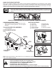
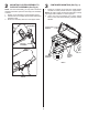
DRAWBAR "A" (See Figs. 1A, 1B & 1C)
1. Removeanddiscardtheupperboltonbothsidesof
thedrawbar.Usingthesameholes,installtheshoulder
bolts supplied and tighten securely.
FIG. 1A
FIG. 1C
2. Installadaptertobothsidesofsupportassemblyas
shown.
BAGGER SUPPORT ASSEMBLY
Determinewhichtypedrawbaryouhaveonyourtractor.
Compare the drawbar illustrations below to the drawbar
located at the rear of your tractor.
Followthesupportassemblyinstructionsthatapplytoyour
type drawbar.
DRAWBAR "A"
DRAWBAR "B"
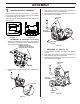
3. Alignsupportassemblypinwithholeindrawbarand
hang assembly over the shoulder bolts.
4. Besuresupportassemblyisseatedproperlyandsecure
with retainer spring supplied.
DRAWBAR "B" (See Fig. 1D)
1. Discardadaptersprovided-notrequiredfordrawbar
typeB.
2. Alignsupportassemblypinwithholeindrawbarand
hang assembly over the shoulder bolts.
3. Besuresupportassemblyisseatedproperlyandsecure
with retainer spring supplied.
FIG. 1D
FIG. 1B
02531
DRAWBAR
REMOVE AND DISCARD
UPPER BOLTS AND INSTALL
SHOULDER BOLTS SUPPLIED
02530
SHOULDER
BOLTS
SUPPORT
ASSEMBLY
RETAINER
SPRING
PIN
3064
SHOULDER
BOLTS
SUPPORT
ASSEMBLY
RETAINER
SPRING
PIN
02530
ADAPTER