Operator’s Manual ST 111 Gasoline containing up to 10% ethanol (E10) is acceptable for use in this machine. The use of any gasoline exceeding 10% ethanol (E10) will void the product warranty. 115 68 68-25 Rev. 6 Please read the owner's manual carefully and make sure you understand the instructions before using the machine.
CONGRATULATIONS on your purchase of a new snow thrower. It has been designed, engineered and manufactured to give best possible dependability and performance. Should you experience any problem you cannot easily remedy, please contact your nearest authorized service center. We have competent, well-trained technicians and the proper tools to service or repair this unit. Please read and retain this manual. The instructions will enable you to assemble and maintain your snow thrower properly.
Operation Maintenance and Storage 1. Do not put hands or feet near or under rotating parts. Keep clear of the discharge opening at all times. 2. Exercise extreme caution when operating on or crossing gravel drives, walks, or roads. Stay alert for hidden hazards or traffic. 3. After striking a foreign object, stop the engine (motor), disconnect the cord on electric motors, thoroughly inspect the snow thrower for any damage, and repair the damage before restarting and operating the snow thrower. Remove key.
TABLE OF CONTENTS SAFETY RULES .................................................................. 2-3 CUSTOMER RESPONSIBILITIES.......................................... 3 PRODUCT SPECIFICATIONS ................................................ 3 SAFETY AND INSTRUCTIONAL DECALS ........................... 4 ASSEMBLY .......................................................................... 5-7 PRODUCT OVERVIEW .......................................................... 8 OPERATION ...........................
ASSEMBLY Setup Loose Parts Use the chart below to verify that all parts have been shipped. Procedure Description Qty. Use 1. 2. No parts required – Unfold the handle. Carriage bolts Flange nuts Washers Knob Chute Deflector 5 4 2 1 1 1 Install the discharge chute. Install the discharge chute. Install the discharge chute. Install the discharge chute. Install the discharge chute. Install the discharge chute. 3. 4. Screw 4 Install the upper handle cover.
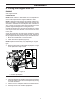
ASSEMBLY 2. Installing the Discharge Chute 3. Installing the Upper Handle Cover Procedure 1. Install the upper handle cover to the handles using four screws (Figure 5). 1. Install the chute deflector to the discharge chute using bolts and, washer, nut, deflector knob and cap plunger (Figure 4). 2. Install the discharge chute to the chute base using three screws and nuts. 7 10 8 1 9 5 4 1 6 2 3 3 2 2 Figure 5 1. Upper handle cover 2. Screws Figure 4 1. 2. 3. 4. 5.
ASSEMBLY 4. Filling the Engine with Oil ENGINE See engine manual. LUBRICATION NOTE: SAE 10W30 or SAE 5W30 oil is acceptable for use in cold temperatures if engine is difficult to start. NOTE: Although multi-viscosity oils (5W30, 10W30 etc.) improve starting in cold weather, these multi-viscosity oils will result in increased oil consumption when used above 32°F. Check your engine oil level more frequently to avoid possible engine damage from running low on oil.
PRODUCT OVERVIEW Product Overview 2 12 11 1 16 3 4 9 10 8 15 *7 *7 6 14 5 Figure 7 1. 2. 3. 4. 5. Discharge chute Chute deflector Fuel tank cap Primer Electric-start button (if equipped) 6. Oil drain plug 7. Oil fill cap/dipstick 8. Choke lever 9. 10. 11. 12. 13. 14. 15. 16. Ignition key Chute rotator handle Recoil start handle Control bar Drive side cover Auger blade Deflector knob Owner's Manual * Dipstick location may vary depending on engine type.
OPERATION Operation Checking the Engine Oil Level NOTE: Determine the left and right sides of the machine from the normal operating position. 1. Move the snowthrower to a level surface. 2. Clean around the dipstick (Figure 9). NOTE: Dipstick location may vary depending on engine type. • Gasoline is extremely flammable and explosive. A fire or explosion from gasoline can burn you and others.
OPERATION Starting the Engine 1. Push key in (Figure 10). 2. Move choke lever to left position. 3. Firmly push in the primer 2 times with your thumb, holding the primer in a for a second before releasing it each time. NOTE: Remove your glove when you push in the primer so that air cannot escape from the primer hole. IMPORTANT: It may not be necessary to use the primer or the choke if the engine has been running and is hot. Excessive priming may flood the engine and prevent it from starting.
OPERATION Engaging the Auger Blades IMPORTANT: During initial operation there may be wear between the auger blades and the scraper bar. Maximum performance, both snow throwing and driving, occurs when there is zero clearance between these two parts (Figure 15). 1. To engage the auger blades, hold the control bar against the handle (Figure 13). During initial break-in period of the auger blades it is normal for the auger blades to build up excessive heat if not operated in the snow.
OPERATION Adjusting the Discharge Chute and Chute Deflector Clearing a Clogged Discharge Chute 1. To adjust the discharge chute, move deflector chute handle left or right to desired position (Figure 17). Hand contact with the rotating auger blades inside the discharge chute is the most common cause of injury associated with snow throwers. Never use your hand to clean out the discharge chute. 1 3 2 To clear the chute: 1. SHUT THE ENGINE OFF! 2.
OPERATION Preventing Freeze-up After Use • Operating Tips Let the engine run for a few minutes to prevent moving parts from freezing. Stop the engine, wait for all moving parts to stop, and remove ice and snow from the snowthrower. • Clean off any snow and ice from the base of the chute. • Rotate the discharge chute left and right to free it from any ice buildup.
MAINTENANCE Maintenance NOTE: Determine the left and right sides of the machine from the normal operating position.
MAINTENANCE Inspecting the Auger Blades/ Scraper Bar 5. After draining the used oil, return the snowthrower to the operating position. 6. Install the oil drain plug and torque to 145-150 in-lbs (17 N-m). NOTE: Dipstick location may vary depending on engine type. Before each session, inspect the auger blades for wear. When an auger blade edge or the scraper bar has worn down have an Authorized Service Dealer replace the auger blades and the scraper bar (Figure 21). 7.
MAINTENANCE Servicing the Spark Plug 6. Remove two screws in plenum that hold top cover (Figure 26). 7. Remove the oil fill cap. Use a NGK BPR6ES, Champion RN9YC, or BOSCH WR6DC spark plug or equivalent. 1. 2. 3. 4. 5. 2 Move snow thrower to a level surface. Run snow thrower until all fuel has been depleted. Wait until engine is cool. Rotate the discharge chute so that it faces forward.
MAINTENANCE 12. Unplug electrical wires on back of ignition switch (Figure 28). 13. Pull tube off the back of the primer bulb. 2 0.030 inch (0.76 mm) 4 2 4 Figure 30 1 19. Install the spark plug and torque it to 20–22 ft-lb (27–30 N-m). 20. Connect the spark plug wire to the spark plug (Figure 29). 21. Reattach primer bulb tube to primer bulb and electrical wires on back ignition switch of rear upper cover (Figure 28). 22.
MAINTENANCE Replacing the Drive Belt 4. Install the new auger V-belt and drive pulley, routing it as shown in Figure 33. NOTE: Route the new auger v-belt first around the engine pulley, then the idler pulley, and finally around the drive pulley while pressing down on the front of the idler arm. (Figure 33). If auger V-belt becomes worn, oil-soaked, excessively cracked, frayed, or otherwise damaged, replace the belt. 1. Remove the drive side cover by removing the six screws as shown in (Figure 32). 4 5.
STORAGE Storage ENGINE OIL Drain oil (with engine warm) and replace with clean engine oil. (See “Changing the Engine Oil” section of this manual). STORING THE SNOWTHROWER Immediately prepare your snow thrower for storage at the end of the season or if the unit will not be used for 30 days or more. CYLINDER 1. Remove spark plug. 2. Pour one ounce (29 ml) of oil through spark plug hole into cylinder. 3. Pull recoil starter handle slowly a few times to distribute oil.
TROUBLESHOOTING Troubleshooting See appropriate section in manual unless directed to a service center/department. PROBLEM CAUSE CORRECTION Does not start 1. Safety ignition key is not inserted. 1. Insert safety ignition key. 2. Out of fuel. 2. Fill fuel tank with fresh, clean gasoline. 3. ON/OFF switch is OFF. 3. Move ON/OFF switch to ON position. 4. Choke in OFF position. 4. Move to FULL position. 5. Primer not depressed. 5. Prime as instructed in the Operation section of this manual.
SERVICE NOTES 21
SERVICE NOTES 22
SERVICE NOTES 23
1-800-487-5951 (U.S.) 1-800-805-5523 (Canada) 8:00 AM to 7:00 PM EST 12.07.17 CL/SR Printed in U.S.A.