
Operating Guide


5
ASSEMBLY
Setup
Loose Parts
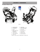
Use the chart below to verify that all parts have been shipped.
Procedure Description Qty. Use
1.
No parts required – Unfold the handle.
2.
Carriage bolts
Flange nuts
Washers
Knob
Chute
Deflector
5
4
2
1
1
1
Install the discharge chute.
Install the discharge chute.
Install the discharge chute.
Install the discharge chute.
Install the discharge chute.
Install the discharge chute.
3.
Screw 4 Install the upper handle cover.
4.
No parts required – Filling the engine with oil
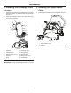
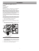
1. Handle
2. Handle adjustment lever
3. Positioning pin
4. Upper handle adjustment hole
Figure 2
1. Unfolding the Handle
Procedure
1. Lift operator handle up to the desired height, and close
adjustment lever ensuring the positioning pin on the
lower handle engages one of the three holes on the
upper handle (Figure 2).
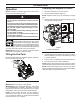
Figure 3
2. Pull up and push down slightly on the handle to verify
handle is locked into place (Figure 3).
NOTE: If handle feels unsecure with the adjustment
levers closed, tighten adjustment handle nuts until the
handle feels secure.
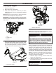
3. Remove the cardboard from recoil start handle and
feed the recoil rope through the rope guide.
1. Recoil handle
2. Rope guide
3. Adjustment lever nut
1
3
4
2
2
3
2
1