Operator’s Manual ST 327T Gasoline containing up to 10% ethanol (E10) is acceptable for use in this machine. The use of any gasoline exceeding 10% ethanol (E10) will void the product warranty. 115 68 66-26 Please read the owner's manual carefully and make sure you understand the instructions before using the machine.
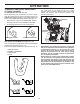
IMPORTANT Safe Operation Practices for Walk-Behind Snow Throwers This snow thrower is capable of amputating hands and feet and throwing objects. Failure to observe the following safety instructions could result in serious injury. WARNING: Snow throwers have exposed rotating parts, which can cause severe injury from contact, or from material thrown from the discharge chute. Keep the area of operation clear of all persons, small children and pets at all times including startup.
6. When cleaning, repairing or inspecting the snow thrower, stop the engine and make certain the collector/ impeller and all moving parts have stopped. Disconnect the spark plug wire and keep the wire away from the plug to prevent someone from accidentally starting the engine. 7. Do not run the engine indoors, except when starting the engine and for transporting the snow thrower in or out of the building. Open the outside doors; exhaust fumes are dangerous. 8.
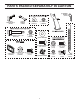
PARTS PACKED SEPARATELY IN CARTON (1) RETAINER SPRINGS (169675) SAFTEY IGNITION KEY (S) (443059) (1) MULTIWRENCH (180684) (6) SHEAR BOLTS 1/4-20 x 1-3/4 (585511801) (1) WASHER 3/8 (19131316) (6) LOCKNUTS 1/4-20 (73800400) (1) LOCKNUT 3/8 (73800600) (2) FLAT WASHERS SKID PLATES (2) CARRIAGE BOLTS 3/8-16 x 2.25 (2) SKID PLATE (583838801) (4) LARGE FLANGE (4) CARRIAGE BOLT 5/16-18 x 1.
ASSEMBLY / PRE-OPERATION Read these instructions and this manual in its entirety before you attempt to assemble or operate your new snow thrower. Reading the entire manual will familiarize you with the unit, which will assist you in assembly, operation and maintenance of the product. Your new snow thrower has been assembled at the factory with the exception of those parts left unassembled for shipping purposes. All parts such as nuts, washers, bolts, etc.
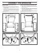
ASSEMBLY / PRE-OPERATION INSTALL TRACTION DRIVE CONTROL ROD (See Figs. 3 and 4) The traction drive control rod is installed on the snow thrower. 1. Remove plastic tie securing traction drive control rod to rotator bracket. 2. With top end of rod positioned under left side of control panel, push rod down and insert top end of rod into hole in traction drive control lever. Snap rod into place by pushing down. NOTE: Engage lever once and rod should snap into place. INSTALL AUGER CONTROL ROD (See Figs.
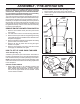
ASSEMBLY / PRE-OPERATION INSTALL DISCHARGE CHUTE / CHUTE ROTATOR HEAD (See Fig. 7) NOTE: The multi-wrench provided in your parts bag may be used to install the chute rotator head. 1. Place discharge chute assembly on top of chute base with discharge opening toward front of snow thrower. 2. Position chute rotator head over chute bracket. If necessary, rotate chute assembly to align square and pin on underside of chute rotator head with holes in chute bracket. 3.
OPERATION KNOW YOUR SNOW THROWER READ THIS OWNER'S MANUAL AND ALL SAFETY RULES BEFORE OPERATING YOUR SNOW THROWER. Compare the illustrations with your snow thrower to familiarize yourself with the location of various controls and adjustments. Save this manual for future reference. These symbols may appear on your snow thrower or in literature supplied with the product. Learn and understand their meaning.
OPERATION MUFFLER CHOKE CONTROL THROTTLE CONTROL AUGER CONTROL LEVER POWER CORD PLUG GASOLINE FILLER CAP DEFLECTOR REMOTE CONTROL LEVER DISCHARGE CHUTE CONTROL LEVER ELECTRIC START BUTTON ON/OFF SWITCH DRIVE SPEED CONTROL LEVER LIGHT TOOLBOX PRIMER SAFETY IGNITION KEY FUEL SHUT-OFF VALVE RECOIL STARTER HANDLE NOTE: ITEMS ABOVE ARE SHOWN IN THEIR TYPICAL LOCATION ON THE ENGINE. ACTUAL LOCATION MAY VARY WITH THE ENGINE ON YOUR UNIT.
OPERATION To operate the height adjust mechanism, using your foot, push down on the pedal, tilt the unit to align the pins with the selected height position and slowly release foot pressure until the pins are seated in the desired height setting. TRANSPORT AND HEIGHT ADJUSTMENT OF SNOW THROWER TO TRANSPORT (See Figs. 11 & 12) When transporting your snowthrower, be sure to disengage the transmission by placing freewheel control into FREEWHEEL position (See Fig.
OPERATION The operation of any snow thrower can result in foreign objects thrown into the eyes, which can result in severe eye damage. Always wear safety glasses or eye shields while operating your snow thrower or performing any adjustments or repairs. We recommend standard safety glasses or a wide vision safety mask worn over spectacles. TO USE THROTTLE CONTROL (See Fig. 16) The throttle control is located on the engine. Always operate the snow thrower with the engine at full throttle.
OPERATION TO MOVE FORWARD AND BACKWARD (See Fig. 20) SELF-PROPELLING, forward and reverse movement of the snow thrower, is controlled by the traction drive control lever located on the left side handle. • Squeeze traction drive control lever to handle to engage the drive system. • Release traction drive control lever to stop the forward or reverse movement of the snow thrower. SPEED and DIRECTION are controlled by the drive speed control lever.
OPERATION POWER STEERING OPERATION (See Fig. 21) Steering triggers are used to assist in steering your snow thrower. The triggers are located on the underside of each handle. When a trigger is squeezed, it disengages the drive wheel on that side of snow thrower and allows it to turn in that direction. • To turn left – squeeze left side trigger. • To turn right – squeeze right side trigger. LH TURN TRIGGER SCRAPER BAR (See Fig. 22) After considerable use the scraper bar may become worn.
OPERATION 4. Rotate choke control to “FULL” position. 5. Connect the power cord to the engine. 6. Plug the other end of the power cord into a three-hole grounded 120 Volt A.C. receptacle. NOTE: Do not use primer when starting engine with the electric starter. 7. Push starter button until engine starts. IMPORTANT: Do not crank engine more than five continuous seconds between each time you try to start. Wait 5 to 10 seconds between each attempt. 8.
OPERATION IF RECOIL STARTER HAS FROZEN If the recoil starter has frozen and will not turn the engine, proceed as follows: 1. Grasp the recoil starter handle and slowly pull as much rope out of the starter as possible. 2. Release the recoil starter handle and let it snap back against the starter. If the engine still fails to start, repeat the above steps or use the electric starter. SNOW THROWING TIPS • • • • • • • • • • • Always operate the snow thrower with the engine at full throttle.
MAINTENANCE GENERAL RECOMMENDATIONS LUBRICATION CHART ➀ SAE 30 Motor Oil ➁ See “ENGINE” in The warranty on this snow thrower does not cover items that have been subjected to operator abuse or negligence. To receive full value from the warranty, operator must maintain snow thrower as instructed in this manual. Some adjustments will need to be made periodically to properly maintain your snow thrower.
MAINTENANCE NOTE: The left side track may be removed from snow thrower for easier access to the oil drain plug and placement of a suitable container. The unit tilted, resting on the frame with the left track removed, will help drain any oil trapped inside the engine. (See “TO REMOVE TRACKS” in the Service and Adjustments section of this manual). 1. Remove safety ignition key and disconnect spark plug wire from spark plug. Place wire where it cannot come in contact with spark plug. 2.
SERVICE AND ADJUSTMENTS IMPELLER SHEAR BOLTS The impeller is secured to the impeller shaft with two (2) capscrew/shear bolts and hex nuts. Should a foreign object or ice become lodged in the impeller, the capscrews are designed to break, preventing damage to any other components. If impeller does not turn when auger control lever is engaged, check to see if the capscrews have sheared. To replace the capscrew/shear bolts: 1. Disengage all controls and move throttle control to STOP position.
SERVICE AND ADJUSTMENTS TO REPLACE BELTS (See Fig. 27) The auger and traction drive belts are not adjustable. If the belts are damaged or begin to slip from wear, they should be replaced. It is recommended that the belt(s) be replaced by a service center/department. NOTE: It is recommended that both the auger and traction drive belt be replaced at the same time.
SERVICE AND ADJUSTMENTS ENGINE TO REMOVE TRACKS (See Fig. 28) 1. Remove cross brace by removing 2 bolts, lock washers and washers from the left and right track assemblies and pulling brace out. 2. Remove the 2 large springs attached to inside of tracks. 3. Remove the klik pin from axle. 4. Pull track off axle. SEE ENGINE MANUAL. CARBURETOR Your carburetor is not adjustable. Engine performance should not be affected at altitudes up to 2,134 meters.
SERVICE AND ADJUSTMENTS NOTE: Figure 33 shows the bellcrank positioned too low, causing hard disengagement or self-disengagement while driving. INSTRUCTIONS FOR ADJUSTING POWER STEERING CABLES (See Figs. 30-35) Power steering cables can be adjusted to improve performance of steering system. The cable has an in-line adjuster that can be turned to shorten or lengthen the cable extension. Location of adjuster is shown in figure 30. LOW POSITION ADJUSTER FIG.
STORAGE ENGINE OIL Drain oil (with engine warm) and replace with clean engine oil. (See “ENGINE” in the Maintenance section of this manual). Immediately prepare your snow thrower for storage at the end of the season or if the unit will not be used for 30 days or more. WARNING: Never store the snow thrower with gasoline in the tank inside a building where fumes may reach an open flame, spark or pilot light as on a furnace, water heater, clothes dryer or gas appliance.
TROUBLESHOOTING See appropriate section in manual unless directed to an authorized service center/department. PROBLEM CAUSE CORRECTION Does not start 1. Fuel shut-off valve (if so equipped) in OFF position. 1. Turn fuel shut-off valve to OPEN position. 2. Safety ignition key is not inserted. 2. Insert safety ignition key. Loss of power 3. Out of fuel. 3. Fill fuel tank with fresh, clean gasoline. 4. Throttle in STOP position (or ON/ OFF switch is OFF). 4.
Consumer Wheeled Products - Limited Warranty Husqvarna warrants to the original retail purchaser that this Husqvarna® product is free from defects in material or workmanship under normal use and maintenance from the date of retail purchase for the applicable Warranty Period shown on Exhibit A. This Limited Warranty may not be transferred to any subsequent purchaser of this Husqvarna® product. Certain components (e.g.
(a) Abrasion to mower decks; (b) Tires damaged by external punctures; (c) Natural discoloration of materials due to ultraviolet light; (d) Damage to cutting equipment by way of contact with, rocks, or other non-approved materials and/or structures; In addition, this Limited Warranty does not cover damages, malfunctions or failures resulting from abuse or neglect of the product related to or including any of the following: (e) Failure to provide or perform required maintenance services as prescribed
Consumer Wheeled Limited Warranty Chart 2013 Product/Component Riding Lawn Tractors: Frame, Chassis, Front Axle Engine* Transmission (if made by Husqvarna/Peerless) Transmission (if third party)** XLS Models only - stamped deck shell.
Consumer Wheeled Limited Warranty Chart 2013 Consumer (personal, household use only) Commercial (any commercial, professional, institutional, agricultural, or income producing use, other than Rental Use) 1 Year 90 days No Warranty No W arranty Product/Component Parts & Accessories (if purchased) Accessories (e.g., grass catcher, bumper guard accessories, etc. Parts (e.g., belts, blades, etc.
05/28/2014 TH