FR GB DE IT ES NL SE PT Manuel d’utilisation - Lire attentivement et bien assimiler le manuel d’utilisation avant d’utiliser la machine. Operator’s manual - Please read the operator’s manual carefully and make sure you understand the instructions before using the machine. Bedienungsanweisung - Lesen Sie die Bedienungsanweisung sorgfältig durch und machen Sie sich mit dem Inhalt vertraut, bevor Sie das Gerät benutzen.
CONTENTS and INTRODUCTION Contents Section Page Contents & Introduction................................................ 3 WARNING! Symbols and Decals....................................................4-8 Before operating machine, read and understand this entire operation manual & engine operation manual supplied with engine. Safety Instructions.....................................................9-13 Be familiar with machine before operation! Parts Identification (What Is What).......................
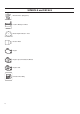
SYMBOLS and DECALS Please read the instructions for use prior to operating the machine for the first time. Emergency Shutdown, Transmission Stop Use In Well Ventilated Area This symbol indicates that the machine is in conformance with the applicable European directive. Mandatory Do Not Use In Flammable Areas Machinery Hazard, Keep hands and Feet Clear. Indication Muffler Hot. May Cause Burns and / or Ignition of Material. Avoid Contact.
SYMBOLS and DECALS Blade Water Safety Switch Electrical Switch-Start Engine Coolant Temperature Repairs Are To Be Done By An Authorized Dealer Only Keep Work Area Clean/Well Lit, Remove All Safety Hazards Headlight Dangerously High Noise Level Diamond Blade Pay Extreme Attention to The Care And Protection Of The Machine Before Starting Up Blade Diameter Blade Engagement Remove Tools From Area and Machine Pulley diameter Engine Oil Pressure Oil Required Number of Revolutions Per Minute, Rotation
SYMBOLS and DECALS Machine Mass (Kilograms) Positive Battery Terminal Blade Depth Indicator – Zero Electric Motor Engine Engine Speed Revolutions/Minute Engine Start Unleaded Fuel Only
SYMBOLS and DECALS P/N 542 19 07-33 Location: Front of Cowl P/N 542 19 07-112 Location: Left and Right Side of Frame (FS 413 Only) P/N 542 19 06-46 Local Service Location: Side of Frame P/N 542 19 05-88 Location: Depth Gauge
SYMBOLS and DECALS P/N 542 16 90-65 Location: Top of Belt Guard P/N 542 19 05-93 Location: Rear of Cowl P/N 502 24 01-05 Location: Top of Cowl P/N 542 19 06-17 Location: Water Tank (If Equipped) P/N 542 19 06-38 Location: Rear of Cowl P/N 543 04 57-88 SOUND LEVEL - 108dBA Location: Upper Righ Hand Frame P/N 542 16 12-35 Location: Upper Righ Hand Frame
SAFETY INSTRUCTIONS General use Fuel Safety: WARNING! Take care when handling fuel. Bear in mind the risk of fire, explosion and inhaling fumes. WARNING! Before operating machine, read and understand this entire operation manual & engine operation manual supplied with engine. Be familiar with machine before operation! Operator must wear personal protective equipment & clothing appropriate to the work he is doing. Personal protective equipment, such as hearing & eye protection, is mandatory.
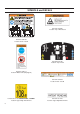
SAFETY INSTRUCTIONS WARNING POISON EXHAUST GAS THIS SAW IS SHIPPED FROM THE FACTORY WITHOUT A CATALYTIC CONVERTER. THE ENGINE PRODUCES CARBON MONOXIDE EXHAUST EMISSIONS AND IS NOT SAFE FOR USE IN ENCLOSED AREAS. USE OF A CATALYTIC CONVERTER REDUCES THE CARBON MONOXIDE EXHAUST EMISSIONS, BUT STILL IS NOT SAFE FOR USE IN ENCLOSED AREAS. USE ONLY IN WELL-VENTILATED AREAS. WORKSITE AIR QUALITY MUST COMPLY WITH OSHA 29 CFR 1910.1000 PER TABLE Z-1, LIMITS FOR AIR CONTAMINANTS.
SAFETY INSTRUCTIONS SAFETY FIRST! WARNINGS DO’s AND DO NOT’s WARNING: FAILURE TO COMPLY WITH THESE WARNINGS AND OPERATING INSTRUCTIONS COULD RESULT IN DEATH OR SERIOUS BODILY INJURY. DO DO DO DO DO DO DO DO DO DO DO DO DO DO DO DO DO DO DO DO DO DO DO DO DO DO DO DO DO DO DO DO DO DO DO DO DO DO Read this entire operator’s manual before operating this machine. Read and understand all warnings, instructions, controls, and symbol definitions contained in this manual, and on the machine.
SAFETY INSTRUCTIONS SAFETY FIRST! WARNINGS DO’s AND DO NOT’s WARNING: FAILURE TO COMPLY WITH THESE WARNINGS AND OPERATING INSTRUCTIONS COULD RESULT IN DEATH OR SERIOUS BODILY INJURY. DO NOT DO NOT DO NOT DO NOT DO NOT DO NOT DO NOT DO NOT DO NOT DO NOT DO NOT DO NOT DO NOT DO NOT DO NOT DO NOT DO NOT DO NOT DO NOT DO NOT DO NOT DO NOT DO NOT DO NOT DO NOT DO NOT DO NOT DO NOT DO NOT DO NOT DO NOT operate this machine unless you have read and understood this operator’s manual.
NOTES 13
PARTS IDENTIFICATION (WHAT IS WHAT) A. Front Pointer: Use to Guide machine in a straight line. B. Guide Wheel: On Front Pointer (A). Align to cutting line and Blade (H) to produce straight cuts. C. Blade Guard: Covers Blade (H). Must always be in place when operating machine! Note tool direction as marked on guard with an arrow. D. Blade Guard Front: Part of Blade Guard. Can be raised to install Blade (H). E. Blade Guard Rear Bolt: Holds Blade Guard (C) in position.
PARTS IDENTIFICATION (WHAT IS WHAT) AA. Emergency Stop Switch: Depress Switch to STOP engine in emergencies. Reset by pulling outward (pull up) to allow re-starting of machine. BB. Tool Compartment: Contains Operation Manual, Parts List, & two wrenches (T & U) (13mm & 27mm). Open by turning knob 180 degrees. Always return Operation Manual to this area for future reference. II. – – – JJ. Rear Handle: Operator position is behind machine with both hands on Rear Handle.
ASSEMBLY Assemble the following items before operating machine for the first time. Re-Position Rear Handle (JJ): Rear Handle (JJ) is shipped in storage position shown. It must be repositioned to use the machine.
ASSEMBLY Install Front Pointer (A): 1. Using screws, washers and nuts installed in the Front Pointer (A), install onto tube frame of Water Tank Support (N). Adjust locking nuts to allow Pointer (A) to pivot freely. 2. Route pointer rope to avoid hot surfaces. Two loops in rope allow attachment to Rear Handle (JJ). Note: “Single Pointer” (A) shown. Some regions have “Dual Pointer” as standard equipment. For all regions, Dual Pointer is available as an accessory.
ASSEMBLY Install Water Tank (P) (if equipped): • A factory installed water tank is available in some regions. An optional water tank kit is available for all regions. • If water tank was previously installed on machine, read these instructions to verify that installation is correct. Follow all WARNINGS for installation and use of the Water Tank. • Verify the contents of the Water Tank Kit See Diagram at right. 1.
ASSEMBLY 4. Position Water Tank, and route Water Tank Hose as shown in Diagram at right. 5. Align rear bar and recessed area at rear of water tank. • Press down firmly on water tank so it snaps in position onto rear bar. • When properly installed, water tank should pivot freely on rear bar. 6. Disconnect existing water hose from blade guard. This is the water hose from water control valve mounted on saw.
ASSEMBLY 7. Connect Water tank hose to blade guard water valve. • Verify that blade guard water valve is in the OFF position. • The water tank hose is now assembled to the saw. Filling Water Tank: 8. Remove the cap by turning counter clockwise. See diagram at right. • Fill water tank only with water. Read all WARNINGS before using water tank. • Re-install the cap by turning clockwise.
OPERATION Before Operation: Use: This machine is used only for wet or dry sawing of old and new concrete and asphalt. WARNING! WARNING! Before operating machine, read and understand this entire operation manual & engine operation manual supplied with engine. Be familiar with machine before operation! DO NOT use for dry cutting in European Union (EU) regions. Machine is not equipped with a dust port. Tools: Use machine only with the following tools (H): Water Cooled Diamond Blades.
OPERATION Transporting & Lifting Machine: • Lift machine only from Lifting Point (O). • Always remove Blade (H) before lifting, loading, or transporting. • Use a proper lifting strap rated for at least the maximum mass of the machine. The nominal and maximum mass of the machine are shown in the TECHNICAL DATA section of this document. Remove Blade (H) before lifting, loading, or transporting machine. Lifting machine equipped with Water Tank: • Before lifting a machine equipped with a water tank: 1.
OPERATION Parking Brake - Dis-engage (See Dia gram): Parking brake must be dis-engaged to operate machine. 1. Pull lever (OO) toward center of machine. 2. Rotate lever (OO) downward 180 degrees and release to lock in position. Gasoline Engine Models: Refer to the engine operating manual for proper engine operation. FUEL: Unleaded gasoline is recommended. See engine operation manual for more information. OIL: Check that engine oil level is correct using the Engine Oil Dipstick (Z).
OPERATION Fitting the Diamond Blade (H): Install Diamond Blade (H) at job site. Do not transport the machine with the Diamond Blade (H) installed. 1. Open Front Cover (V). 2. Set Engine Start Switch (DD) to OFF (“0”) position. 3. Raise Diamond Blade (H) to highest position by turning Blade Depth Control (EE) Counter-Clockwise. 4. Use 13mm Wrench (U) located in Tool Compartment (BB), to loosen and remove four (4) M8 bolts that attach Blade Guard Latch Plate (F).
OPERATION Starting and cutting with machine: • Using the Depth Control (EE), raise Diamond Blade (H) as high as possible so it will not strike pavement when maneuvering. Pull out on Blade Depth Stop (FF) if required. • Dis-engage parking brake (if equipped). • Maneuver machine into position near line to be cut. • Lower Front Pointer (A) onto cutting surface. • Set Depth Indicator (GG) (use if desired): 1) Lower machine until diamond blade contacts cutting surface.
MAINTENANCE & LUBRICATION SCHEDULED MAINTENANCE QUICK REFERENCE: Before performing any maintenance, ALWAYS park the machine on a level surface with the engine “OFF” and the engine switch set in the “OFF” position. Let the machine cool down! Other maintenance and repairs should only be carried out by a qualified technician. SERVICE DAILY: 1. Check engine oil level. 2. Check blade guard for damage. 3. Check engine air filter, replace if dirty. Service sooner if used in dusty conditions. 4.
MAINTENANCE & LUBRICATION LUBRICATION: Depth Control Grease Fitting (X): A grease fitting allows lubrication of Blade Depth Control (EE) screw. To access this grease fitting: • Raise the Diamond Blade (H) to maximum height. Open Tool Compartment (BB), temporarily remove operation manual bag. • Grease fitting (X) is located near top of Blade Depth Control (EE) Tube. • Add Grease to the fitting. Raise and lower the machine a few times to circulate the grease through the tube.
MAINTENANCE & LUBRICATION Blade Shaft Drive Belt Tension: Drive Belt should be re-tensioned after first few hours of operation. Belt Drive Idler (MM) holds tension on Drive Belt. Tools Required: • 13mm Wrench (Included with machine). • 3/8” (9.53mm) Drive Torque Wrench (Not Included) • 14mm Wrench (Not included with machine). 1. Use 13mm Wrench (U), to remove three (3) M8 bolts that attach Belt Guard (LL). Remove Guard (LL). 2.
TROUBLE SHOOTING GUIDE Engine Will Not Start: Cause Action Electrical switches not in correct position. Check that BOTH Emergency Stop Switch (AA) and Engine Start Switch (DD) are in “ON” position. Emergency Stop Switch (AA) should be pulled outward from cowl, and Engine Start Switch (DD) turned to “1” (ON) position. Fuel valve closed. Open the fuel valve. Choke valve open. Close the choke with cold engine. Fuel tank empty. Fill with fuel. Contamination, or water ice in fuel system.
WIRING DIAGRAM 30
TECHNICAL DATA Machine Mass Noise emissions (see note 1) Nominal Mass, kg 124 Sound power level, measured dB(A) 103 Maximum Mass, kg 158 Sound power level, guaranteed dB(A) 104 Blade shaft and engine speed Blade shaft, RPM 2600 Engine, RPM 3600 Water Tank Capacity Litres US Gallons (U.K. Gallons) 25 6.6 (5.
ACCESSORIES Dual Pointer Assembly 542 20 22-70 Complete Kit Water Tank Assembly 541 20 82-86 Complete Kit 33
CONFORMITY CERTIFICATES American National Standards Institute : For units used in the United States, this machine has been designed to comply with American National Standards Institute ANSI B7.1-2000, “Safety Requirements for the Use, Care and Protection of Abrasive Wheels”. This standard can be purchased by contacting the American National Standards Institute at the address shown below: American National Standards Institute 25 West 43rd Street, 4th floor New York, NY 10036 Telephone: 212.642.
CONTACT INFORMATION Construction Products, North America Corporate Office 17400 West 119th Street, Olathe, Kansas 66061 USA Corporate Office: 913-928-1000 Corp. Office Fax: 913-438-7951 www.husqvarna.com For local service, please contact your local Husqvarna Construction Products representative. Para efectuar un servicio local, póngase en contacto con su representante local de Husqvarna Construction Products. Pour toute réparation, contacter le représentant local de Husqvarna Construction Products.
CONTENIDO e INTRODUCCIÓN Contenido Sección Página Contenido e introducción.............................................37 Símbolos y calcomanías.........................................38–42 Instrucciones de seguridad....................................43–46 Identificación de piezas (qué es qué)....................48–49 Ensamblado.............................................................50–54 Funcionamiento.......................................................55–59 Mantenimiento y lubricación...........
SÍMBOLOS y CALCOMANÍAS Lea las instrucciones de uso antes de operar la máquina por primera vez. Parada de emergencia, detener la transmisión Usar en un área bien ventilada Este símbolo indica que la máquina cumple con las directivas pertinentes de la Unión Europea.
SÍMBOLOS y CALCOMANÍAS Conmutador de seguridad de agua de la cuchilla Interruptor eléctrico – Arranque (Start).
SÍMBOLOS y CALCOMANÍAS Peso de la máquina (kilogramos) Terminal positivo de la batería Indicador de profundidad de la cuchilla – Cero Motor eléctrico Motor Velocidad del motor, revoluciones / minuto Puesta en marcha del motor Usar combustible sin plomo solamente 40
SÍMBOLOS y CALCOMANÍAS P/N 542 19 07-33 Location: Front of Cowl P/N 542 19 07-112 Location: Left and Right Side of Frame (FS 413 Only) P/N 542 19 06-46 Local Service Location: Side of Frame P/N 542 19 05-88 Location: Depth Gauge 41
SÍMBOLOS y CALCOMANÍAS P/N 542 16 90-65 Location: Top of Belt Guard P/N 542 19 05-93 Location: Rear of Cowl P/N 502 24 01-05 Location: Top of Cowl P/N 542 19 06-17 Location: Water Tank (If Equipped) P/N 542 19 06-38 Location: Rear of Cowl P/N 543 04 57-88 SOUND LEVEL - 108dBA Location: Upper Righ Hand Frame 42 P/N 542 16 12-35 Location: Upper Righ Hand Frame
INSTRUCCIONES DE SEGURIDAD Seguridad sobre el combustible: Uso general ¡ADVERTENCIA! Antes de operar la máquina, lea íntegramente y comprenda este manual de operación y el manual de operación del motor provisto con el mismo. ¡Familiarícese con la máquina antes de utilizarla! El operador debe utilizar equipo protector personal e indumentaria acorde al tipo de trabajo a realizar. Es obligatorio el uso de equipo protector personal, como protección auditiva y ocular.
INSTRUCCIONES DE SEGURIDAD ADVERTENCIA GAS DE ESCAPE TÓXICO ESTA SIERRA SE ENVÍA DE FÁBRICA SIN CONVERSOR CATALÍTICO. EL MOTOR PRODUCE EMISIONES DE ESCAPE DE MONÓXIDO DE CARBONO Y NO ES SEGURO UTILIZARLO EN ÁREAS CERRADAS. AUNQUE EL USO DE UN CONVERSOR CATALÍTICO DISMINUYE LAS EMISIONES DE ESCAPE DE MONÓXIDO DE CARBONO, NO ES SEGURO UTILIZAR LA MÁQUINA EN ÁREAS CERRADAS. UTILÍCESE SOLAMENTE EN ÁREAS BIEN VENTILADAS.
INSTRUCCIONES DE SEGURIDAD ¡LA SEGURIDAD ES LO PRIMERO! ADVERTENCIAS LOS SÍ Y LOS NO ADVERTENCIA: EL INCUMPLIMIENTO DE ESTAS ADVERTENCIAS E INSTRUCCIONES DE OPERACIÓN PUEDE RESULTAR EN MUERTE O ACCIDENTES PERSONALES GRAVES. SÍ SÍ SÍ SÍ SÍ SÍ SÍ SÍ SÍ SÍ SÍ SÍ SÍ SÍ SÍ SÍ SÍ SÍ SÍ SÍ SÍ SÍ SÍ SÍ SÍ SÍ SÍ SÍ SÍ SÍ SÍ SÍ SÍ SÍ SÍ SÍ SÍ SÍ Lea íntegramente este manual del operador antes de utilizar la máquina.
INSTRUCCIONES DE SEGURIDAD ¡LA SEGURIDAD ES LO PRIMERO! ADVERTENCIAS LOS SÍ Y LOS NO ADVERTENCIA: EL INCUMPLIMIENTO DE ESTAS ADVERTENCIAS E INSTRUCCIONES DE OPERACIÓN PUEDE RESULTAR EN MUERTE O ACCIDENTES PERSONALES GRAVES. NO NO NO NO NO NO NO NO NO NO NO NO NO NO NO NO NO NO NO NO NO NO NO NO NO NO NO NO NO NO NO Opere la máquina si no ha leído y comprendido el manual del operador. Opere la máquina si el protector de la cuchilla u otros elementos protectores no están en su sitio.
NOTAS 47
IDENTIFICACIÓN DE LAS PIEZAS (QUÉ ES QUÉ) A. Puntero delantero: úselo para guiar la máquina en línea recta. B. Rueda de guía: ubicada en el puntero delantero (A). Alinéela con la línea de corte y con la cuchilla (H) para obtener cortes rectos. C. Protección de la cuchilla: cubre la cuchilla (H). ¡Debe estar siempre en su sitio al operar la máquina! Observe la dirección de la herramienta según se marca en la protección con una flecha. D.
IDENTIFICACIÓN DE LAS PIEZAS (QUÉ ES QUÉ) Y. Espada de montaje de la protección de la cuchilla: mantiene la protección de la cuchilla (C) en su sitio. Z. Varilla de medición de aceite del motor: úsela para controlar el nivel de aceite del motor (no se ilustra, consulte la sección Operación de este documento). AA Interruptor de parada de emergencia: oprima el interruptor para DETENER el motor en caso de emergencias. Para restaurar, tire hacia fuera (levántelo) para volver a arrancar la máquina. BB.
ENSAMBLADO Antes de operar la máquina por primera vez ensamble los elementos siguientes. Vuelva a posicionar el manubrio trasero (JJ): la máquina se envía con el manubrio trasero (JJ) en posición de guardado, tal como se ilustra. Para usar la máquina, el manubrio se debe volver a posicionar.
ENSAMBLADO Instale el puntero delantero (A): 1. Use los tornillos, arandelas y tuercas del puntero delantero (A) e instálelos en el cuadro tubular del soporte del tanque de agua (N). Ajuste las contratuercas de manera tal que el puntero (A) pivote libremente. 2. Disponga la cuerda del puntero de manera tal que no pase por superficies calientes. Los dos bucles de la cuerda permiten engancharla al manubrio trasero (JJ). Nota: Se ilustra el “puntero simple” (A).
ENSAMBLADO Instale el tanque de agua (P) (de incluirse): • En algunas regiones se ofrece un tanque de agua instalado de fábrica. En todos los lugares se ofrece un equipo de tanque de agua opcional. • Si el tanque de agua se instaló previamente en la máquina, lea estas instrucciones para verificar que se haya instalado correctamente. Obedezca todas las ADVERTENCIAS de instalación y uso del tanque de agua. • Verifique el contenido del equipo del tanque de agua. Consulte el diagrama de la derecha. 1.
ENSAMBLADO 4. Presente el tanque de agua y pase la manguera correspondiente tal como se ilustra en el diagrama de la derecha. 5. Alinee la barra trasera y el área ahuecada en la parte posterior del tanque de agua. • Apriete firmemente el tanque de agua para calzarlo en su sitio en la barra trasera. • Cuando se instala correctamente, el tanque de agua debe pivotar libremente en la barra trasera. 6. Desconecte la manguera de agua de la protección de lacuchilla.
ENSAMBLADO 7. Conecte la manguera del tanque de agua a la válvula de agua de la protección de la cuchilla. • Verifique que la válvula de agua de la protección de la cuchilla esté en posición CERRADA (OFF). • El tanque de agua queda ya montado en la sierra. Llenado del tanque de agua: 8. Gire la tapa en sentido antihorario para quitarla. Consulte el diagrama de la derecha. • Llene el tanque solamente con agua. Lea todas las ADVERTENCIAS antes de usar el tanque de agua.
FUNCIONAMIENTO Antes de poner en funcionamiento: Uso: esta máquina se debe usar solamente para cortes en seco o húmedos de asfalto u hormigón, tanto viejo como nuevo. ¡ADVERTENCIA NO utilizar para cortes en seco en regiones de la Unión Europea (EU) La máquina no incluye un puerto para polvo. Herramientas: use la máquina solamente con las herramientas siguientes (H): cuchillas adiamantadas enfriadas con agua.
FUNCIONAMIENTO Transporte e izado de la máquina: • Sólo levante la máquina desde el punto de izado (O). • Siempre quite la cuchilla (H) antes de levantar, cargar o transportar la máquina. • Use una banda de izado debidamente clasificada para levantar como mínimo el peso máximo de la máquina. El peso nominal y máximo de la máquina se indican en la sección DATOS TÉCNICOS de este documento. Izado de la máquina equipada con el tanque de agua: • Antes de levantar una máquina equipada con un tanque de agua: 1.
FUNCIONAMIENTO F reno de estacionamientoDesactivación (Véase diagrama) Para operar la máquina, desactive el freno de estacionamiento. 1. Tire de la palanca (OO) hacia el centro de la máquina. 2. Rote la palanca (OO) hacia abajo 180 grados y suéltela para trabarla en su sitio. Modelos con motor a gasolina: Para el correcto funcionamiento, consulte el manual de operación del motor. COMBUSTIBLE: se recomienda el uso de gasolina sin plomo. Para más información, consulte el manual de operación del motor.
FUNCIONAMIENTO Colocación de la cuchilla adiamantada (H): I nstale la cuchilla adiamantada (H) en la obra. No trasporte la máquina con la cuchilla adiamantada (H) instalada. 1. Abra la cubierta delantera (V). 2. Coloque el interruptor de arranque del motor (DD) en la posición APAGADO / OFF (“0”). 3. Gire el control de profundidad de la cuchilla (EE) en sentido antihorario para levantar la cuchilla adiamantada (H) hasta la posición más alta. 4.
FUNCIONAMIENTO Arranque de la máquina y proceso de corte: • Con el control de profundidad (EE), levante la cuchilla adiamantada (H) a la mayor altura posible para evitar que al maniobrar choque con el pavimento. Si fuera necesario, tire del tope de profundidad de la cuchilla (FF). • Desactive el freno de estacionamiento (si se incluye). • Coloque la máquina en posición, cerca de la línea a cortar. • Baje el puntero delantero (A) hasta la superficie de corte.
MANTENIMIENTO Y LUBRICACIÓN REFERENCIA RÁPIDA DE MANTENIMIENTO PROGRAMADO: Antes de realizar tareas de mantenimiento, SIEMPRE recuerde estacionar la máquina en una superficie nivelada, con el motor “y el interruptor de motor en la posición “APAGADO / OFF”. ¡Deje que la máquina se enfríe! Las tareas de mantenimiento y reparaciones adicionales deben ser realizadas solamente por un técnico cualificado. SERVICIO DIARIO: 1. Controle el nivel de aceite del motor. 2.
MANTENIMIENTO Y LUBRICACIÓN LUBRICACIÓN: Accesorio de engrase para el control de profundidad (X): un accesorio de engrase que permite la lubricación del tornillo de control de profundidad (EE) de la cuchilla. Para acceder a este accesorio de profundidad: • Levante la cuchilla adiamantada (H) hasta la altura máxima. Abra el compartimento de herramientas (BB), quite provisoriamente la bolsa que contiene el manual.
MANTENIMIENTO Y LUBRICACIÓN Tensión de la correa de transmisión del eje de la cuchilla: después de unas pocas horas de uso se debe volver a ajustar la tensión de la correa de transmisión. El piñón de la correa de transmisión (MM) mantiene la tensión de la misma. Herramientas necesarias: • Llave de 13 mm (se incluye con la máquina) • Llave aprieta tuercas de 9,53 mm (3/8 pulgada) (no se incluye) • Llave de 14 mm (no se incluye con la máquina) 1.
GUÍA PARA LA DETERMINACIÓN Y RESOLUCIÓN DE PROBLEMAS El motor no arranca: Causa Acción Los interruptores eléctricos no están en la posición correcta. Verifique que TANTO el interruptor de parada de emergencia (AA) COMO el interruptor de arranque del motor (DD) estén en la posición de ENCENDIDO / ON. El interruptor de parada de emergencia (AA) se debe tirar hacia afuera desde la cubierta, y el interruptor de arranque del motor (DD) se debe girar a la posición “1” (ENCENDIDO/ON).
DIAGRAMA DE CABLEADO 64
DONNÉES TECHNIQUES Masse de la machine Émissions sonores (voir remarque 1) Masse nominale, kg 124 Niveau de puissance sonore mesuré dB(A) 103 Masse maximale, kg 158 Niveau de puissance sonore garanti dB(A) 104 Vitesse d’axe et régime moteur Niveaux sonores (voir remarque 2) Vitesse d’axe, tr/min 2600 Niveau de pression acoustique au niveau des oreilles de l’utilisateur, dB(A) Régime moteur, tr/min 3600 Niveaux de vibrations, ahv (voir remarque 3) Capacité du réservoir d’eau Litres Gallons
ACCESORIOS Ensamblado del puntero doble Conjunto completo 542 20 22-70 Ensamblado del tanque de agua Conjunto completo 541 20 82-86 67
CERTIFICADOS DE CUMPLIMIENTO Instituto Estadounidense de Normas Nacionales (American National Standars Institute): para unidades utilizadas en los Estados Unidos, esta máquina ha sido diseñada en cumplimiento de la norma ANSI B7.1-2000, “Requisitos de seguridad para el uso, cuidado y protección de ruedas abrasivas” del Instituto Estadounidense de Normas Nacionales (ANSI).
INFORMACIÓN DE CONTACTO Husqvarna Construction Products, North America Sede Social 17400 West 119th Street, Olathe, Kansas 66061 Estados Unidos Sede Social: 913-928-1000 Fax de la sede social: 913-438-7951 www.husqvarna.com Para efectuar un servicio local, póngase en contacto con su representante local de Husqvarna Construction Products.
SOMMAIRE et INTRODUCTION Sommaire Section Page Sommaire et introduction.............................................71 Symboles et autocollants.......................................72–76 Instructions de sécurité..........................................77–80 Identification des pièces.........................................82–83 Assemblage.............................................................84–88 Fonctionnement.......................................................
SYMBOLES et AUTOCOLLANTS Veiller à lire les instructions d’utilisation avant d’utiliser la machine pour la première fois. Arrêt d’urgence, débrayage de la transmission Utiliser dans un endroit bien aéré Ce symbole indique que la machine est conforme à la directive européenne applicable. Obligatoire Ne pas utiliser dans des lieux où se trouvent des matières inflammables Risques présentés par la machine ; garder les mains et les pieds éloignés.
SYMBOLES et AUTOCOLLANTS Interrupteur de sécurité de l’eau du disque Commutateur électrique - Démarrage Température du liquide de refroidissement du moteur Les réparations ne doivent être effectuées que par un concessionnaire agréé Maintenir la zone de travail propre et bien éclairée ; enlever tout ce qui constitue un danger Phare Niveau de bruit élevé, dangereux Accorder une très grande attention à l’entretien et aux protections de la machine avant de la mettre en marche Disque diamanté Diamètre d
SYMBOLES et AUTOCOLLANTS Masse de la machine (kg) Borne positive de batterie Indicateur de profondeur de disque – zéro Moteur électrique Moteur Régime moteur, tours/minute Démarrage du moteur Carburant sans plomb uniquement 74
SYMBOLES et AUTOCOLLANTS P/N 542 19 07-33 Location: Front of Cowl P/N 542 19 07-112 Location: Left and Right Side of Frame (FS 413 Only) P/N 542 19 06-46 Local Service Location: Side of Frame P/N 542 19 05-88 Location: Depth Gauge 75
SYMBOLES et AUTOCOLLANTS P/N 542 16 90-65 Location: Top of Belt Guard P/N 542 19 05-93 Location: Rear of Cowl P/N 502 24 01-05 Location: Top of Cowl P/N 542 19 06-17 Location: Water Tank (If Equipped) P/N 542 19 06-38 Location: Rear of Cowl P/N 543 04 57-88 SOUND LEVEL - 108dBA Location: Upper Righ Hand Frame 76 P/N 542 16 12-35 Location: Upper Righ Hand Frame
INSTRUCTIONS DE SÉCURITÉ Carburant : Généralités AVERTISSEMENT ! Avant d’utiliser la machine, lire et comprendre ce manuel d’utilisation en entier et le manuel d’utilisation du moteur fourni avec le moteur. Veiller à se familiariser avec la machine avant utilisation ! L’utilisateur doit porter un équipement de protection individuelle et des vêtements adaptés au travail à effectuer. L’équipement de protection individuelle, notamment protection des yeux et des oreilles, est obligatoire.
INSTRUCTIONS DE SÉCURITÉ AVERTISSEMENT GAZ D’ÉCHAPPEMENT TOXIQUES CETTE SCIE EST EXPÉDIÉE DE L’USINE SANS CONVERTISSEUR CATALYTIQUE. CE MOTEUR DÉGAGE DES GAZ D’ÉCHAPPEMENT CONTENANT DE L’OXYDE DE CARBONE ET IL EST DANGEREUX DE L’UTILISER DANS DES ENDROITS CLOS. L’EMPLOI D’UN CONVERTISSEUR CATALYTIQUE RÉDUIT LES ÉMISSIONS D’OXYDE DE CARBONE DANS LES GAZ D’ÉCHAPPEMENT, MAIS IL EST TOUJOURS DANGEREUX DE L’UTILISER DANS DES ENDROITS CLOS. NE L’UTILISER QUE DANS DES ENDROITS BIEN VENTILÉS.
INSTRUCTIONS DE SÉCURITÉ SÉCURITÉ D’ABORD ! CONSIGNES DE SÉCURITÉ A FAIRE ET À NE PAS FAIRE AVERTISSEMENT : LE NON-RESPECT DE CES CONSIGNES DE SÉCURITÉ ET DES INSTRUCTIONS D’UTILISATION RISQUE D’ENTRAÎNER DES BLESSURES GRAVES OU MORTELLES. A FAIRE A FAIRE Lire ce manuel d’utilisation en entier avant d’utiliser cette machine. Lire et comprendre tous les avertissements, instructions, commandes et définitions de symboles figurant dans ce manuel et sur la machine.
INSTRUCTIONS DE SÉCURITÉ SÉCURITÉ D’ABORD ! CONSIGNES DE SÉCURITÉ A FAIRE ET À NE PAS FAIRE AVERTISSEMENT : LE NON-RESPECT DE CES CONSIGNES DE SÉCURITÉ ET DES INSTRUCTIONS D’UTILISATION RISQUE D’ENTRAÎNER DES BLESSURES GRAVES OU MORTELLES.
NOTES 81
IDENTIFICATION DES PIÈCES A. Flèche avant : Sert à guider la machine en ligne droite. B. Galet guide : Sur la flèche avant (A). S’aligne sur la ligne de coupe et sur le disque (H) pour produire des coupes droites. C. Protège-disque : Couvre le disque (H). Doit toujours être en place lors de l’utilisation de la machine ! Noter le sens de l’outil, indiqué par une flèche sur le protège-disque. D. Avant du protège-disque : Un élément du protègedisque. Se soulève pour poser le disque (H). E.
IDENTIFICATION DES PIÈCES Z. Jauge d’huile du moteur : Sert à contrôler le niveau d’huile du moteur (non représentée - voir la section Utilisation de ce document). AA. Interrupteur d’arrêt d’urgence : Enfoncer l’interrupteur pour ARRÊTER le moteur en cas d’urgence. Se réarme en tirant le bouton vers l’extérieur (vers le haut) pour permettre le redémarrage de la machine. BB. Compartiment à outils : Contient le manuel d’utilisation, la liste des pièces détachées et deux clés (T et U) (13 mm et 27 mm).
ASSEMBLAGE Assembler les éléments suivants avant d’utiliser la machine pour la première fois. Mettre le guidon (JJ) en position correcte : Le guidon (JJ) est livré dans la position de rangement montrée sur l’illustration. Il doit être relevé pour pouvoir utiliser la machine.
ASSEMBLAGE Poser la flèche avant (A) : 1. À l’aide des vis, rondelles et écrous fournis, poser la flèche avant (A) sur le cadre tubulaire du support de réservoir d’eau (N). Ajuster les écrous-freins de manière à permettre à la flèche (A) de pivoter librement. 2. Faire passer la corde de la flèche à l’écart des surfaces chaudes. Les deux boucles dans la corde permettent de l’attacher au guidon (JJ). Remarque : « Flèche simple » (A) montrée sur l’illustration.
ASSEMBLAGE Poser le réservoir d’eau (P) (le cas échéant) : • Dans certaines régions, la machine peut être livrée avec un réservoir d’eau installé. Le réservoir d’eau est proposé sous forme de nécessaire en option dans toutes les régions. • Si un réservoir d’eau est déjà posé sur la machine, lire ces instructions pour vérifier que la pose est correcte. Respecter tous les AVERTISSEMENTS concernant la pose et l’utilisation du réservoir d’eau. • Vérifier le contenu du nécessaire de réservoir d’eau.
ASSEMBLAGE 4. Mettre le réservoir d’eau en place et acheminer le flexible d’eau comme sur l’illustration à droite. 5. Aligner la barre arrière et le renfoncement à l’arrière du réservoir d’eau. • Pousser fermement le réservoir vers le bas pour l’enclencher sur la barre arrière. • Lorsqu’il est correctement en place, le réservoir d’eau doit pivot librement sur la barre arrière. 6. Débrancher le flexible d’eau existant du protègedisque.
ASSEMBLAGE 7. Raccorder le flexible du réservoir d’eau au robinet d’eau du protège-disque. • Vérifier que le robinet d’eau du protège-disque est FERMÉ. • Le réservoir d’eau est à présent installé sur la machine. Remplir le réservoir d’eau : 8. Enlever le bouchon en le tournant dans le sens inverse des aiguilles d’une montre. Voir l’illustration à droite. • Remplir le réservoir d’eau uniquement avec de l’eau. Lire tous les AVERTISSEMENTS avant d’utiliser le réservoir d’eau.
UTILISATION Avant utilisation Emploi : Cette machine est uniquement destinée au sciage humide ou sec de béton et d’asphalte neufs et anciens. AVERTISSEMENT ! NE PAS l’utiliser pour le découpage à sec dans les pays de l’Union européenne (UE). La machine n’est pas équipée d’une prise à poussière. Outils : Utiliser la machine exclusivement avec les outils suivants (H) : Disques diamantés refroidis à l’eau.
UTILISATION Transport et levage de la machine : • Soulever la machine uniquement par le point de levage (O). • Toujours déposer le disque (H) avant de lever, charger ou transporter la machine. • Utiliser une sangle de levage d’une capacité nominale au moins égale à la masse maximale de la machine. Les masses nominale et maximale de la machine figurent dans la section DONNÉES TECHNIQUES de ce document.
UTILISATION F rein de stationnement - Libérer (voir illustration) Le frein de stationnement doit être libérer pour pouvoir faire fonctionner la machine. 1. Tirer le levier (OO) vers le centre de la machine. 2. Tourner le levier (OO) de 180 degrés vers le bas et le relâcher pour l’enclencher dans cette position. Modèles à moteur essence : Voir le fonctionnement du moteur dans le manuel d’utilisation du moteur. CARBURANT : L’essence sans plomb est conseillée.
UTILISATION Pose du disque diamanté (H) : e disque diamanté (H) se met en place sur le L chantier. Ne pas transporter la machine avec le disque diamanté (H) en place. 1. Ouvrir le cache avant (V). 2. Mettre le contacteur de démarrage du moteur (DD) en position d’ARRÊT (0). 3. Relever le disque diamanté (H) jusqu’à sa position la plus haute en tournant la commande de profondeur de disque (EE) dans le sens des aiguilles d’une montre. 4.
UTILISATION Démarrer et scier avec la machine : • À l’aide de la commande de profondeur (EE), relever le disque diamanté (H) aussi haut que possible afin de ne pas heurter le sol en manœuvrant. Tirer la butée de profondeur (FF) au besoin. • Libérer le frein de stationnement (le cas échéant). • Mettre la machine en position près de la ligne de coupe. • Abaisser la flèche avant (A) jusqu’à la surface de coupe.
ENTRETIEN ET LUBRIFICATION GUIDE RAPIDE D’ENTRETIEN COURANT : Avant toute opération d’entretien, TOUJOURS stationner la machine sur une surface horizontale, avec le moteur à l’ARRÊT et le contacteur du moteur en position d’ARRÊT. Laisser la machine refroidir ! Les autres opérations d’entretien et de réparations doivent être confiées à un technicien qualifié. À FAIRE CHAQUE JOUR : 1. Vérifier le niveau d’huile moteur. 2. Vérifier que le protège-disque n’est pas endommagé. 3.
ENTRETIEN ET LUBRIFICATION LUBRIFICATION : Graisseur de la commande de profondeur (X) : Un graisseur est prévu pour le graissage de la vis de commande de profondeur du disque (EE). Pour accéder au graisseur : • Relever le disque diamanté (H) jusqu’à sa hauteur maximale. Ouvrir le compartiment à outils (BB) et sortir provisoirement la pochette du manuel d’utilisation. • Le graisseur (X) se trouve près du sommet du tube de la commande de profondeur de disque (EE). • Pomper de la graisse dans le graisseur.
ENTRETIEN ET LUBRIFICATION Tension de la courroie d’entraînement de l’axe de disque : La courroie d’entraînement doit être retendue au bout des quelques premières heures de marche. Le tendeur de courroie (MM) maintient la tension de la courroie d’entraînement. Outillage nécessaire : 1. À l’aide de la clé de 13 mm (U), déposer les trois (3) boulons M8 de fixation du protège-courroie (LL). Déposer le protège-courroie (LL). 2.
GUIDE DE DÉPANNAGE Le moteur ne démarre pas : Cause Action Commutateurs électriques pas dans la bonne position. Vérifier que l’interrupteur d’arrêt d’urgence (AA) ET le contacteur de démarrage (DD) sont TOUS DEUX en position de MARCHE. L’interrupteur d’arrêt d’urgence (AA) doit être tiré vers l’extérieur du capot et le contacteur de démarrage (DD) en position « 1 » (MARCHE). Le robinet de carburant est fermé. Ouvrir le robinet de carburant. Volet de départ ouvert.
SCHÉMA DE CÂBLAGE 98
DONNÉES TECHNIQUES Masse de la machine Émissions sonores (voir remarque 1) Masse nominale, kg 124 Niveau de puissance sonore mesuré dB(A) 103 Masse maximale, kg 158 Niveau de puissance sonore garanti dB(A) 104 Vitesse d’axe et régime moteur Niveaux sonores (voir remarque 2) Vitesse d’axe, tr/min 2600 Niveau de pression acoustique au niveau des oreilles de l’utilisateur, dB(A) Régime moteur, tr/min 3600 Niveaux de vibrations, ahv (voir remarque 3) Capacité du réservoir d’eau Litres Gallons
ACCESSOIRES Flèche double 542 20 22-70 Kit complet Réservoir d’eau 541 20 82-86 Kit complet 101
CERTIFICATS DE CONFORMITÉ American National Standards Institute : Pour les appareils utilisés aux États-Unis, cette machine a été conçue en conformité avec la norme ANSI B7.1-2000, « Safety Requirements for the Use, Care and Protection of Abrasive Wheels » de l’American National Standards Institute.
INFORMATIONS DE CONTACT Construction Products, North America Corporate Office 17400 West 119th Street, Olathe, Kansas 66061 USA Corporate Office: 913-928-1000 Corp. Office Fax: 913-438-7951 www.husqvarna.com Pour toute réparation, contacter le représentant local de Husqvarna Construction Products. Europe : Husqvarna Construction Products SE-433 81 Partille, Suède Tél.
INHALTSVERZEICHNIS und EINLEITUNG Inhaltsverzeichnis Kapitel Seite Inhaltsverzeichnis und Einleitung................................ 3 ACHTUNG! Sicherheitshinweise................................................. 9-13 Lesen Sie vor der Bedienung der Maschine diese Bedienungsanleitung und die mit dem Motor gelieferte Betriebsanleitung gründlich. Beschreibung der einzelnen Teile......................... 14-15 Machen Sie sich vor dem Betrieb mit der Maschine vertraut! Symbole und Aufkleber...............
SYMBOLE und AUFKLEBER Lesen Sie bitte vor der ersten Inbetriebnahme der Maschine die Bedienungsanleitung. Notabschaltung, Getriebeabschaltung. In gut belüftetem Bereich verwenden Dieses Symbol zeigt, dass die Maschine die jeweilige EU-Richtlinie erfüllt. Nicht in feuergefährdeten Bereichen verwenden. Zwingend Warnung vor Handverletzung durch Maschinen, Hände und Füße fernhalten. Angabe Verbot Heißer Auspuff. Kann zu Verbrennungen und/oder Entzündung von Material führen. Berührung vermeiden.
SYMBOLE und AUFKLEBER Sicherheitsschalter für Wasserzufuhr zur Trennscheibe. Elektrischer Startschalter Motorkühlmitteltemperatur Reparaturen dürfen nur vom Vertragshändler durchgeführt werden. Arbeitsbereich muss sauber u. gut beleuchtet sein; sämtliche Gefahrenquellen beseitigen. Scheinwerfer Gefährlich hoher Lärmpegel. Diamanttrennscheibe Vor der Inbetriebnahme sorgfältig auf die Pflege und den Schutz der Maschine achten.
SYMBOLE und AUFKLEBER Gewicht der Maschine (kg) Positive Batterieklemme Trennscheibentiefenanzeige – Null Elektromotor Motor Motordrehzahl in U/min Motoranlasser Nur unverbleites Benzin
SYMBOLE und AUFKLEBER P/N 542 19 07-33 Location: Front of Cowl P/N 542 19 07-112 Location: Left and Right Side of Frame (FS 413 Only) P/N 542 19 06-46 Local Service Location: Side of Frame P/N 542 19 05-88 Location: Depth Gauge
SYMBOLE und AUFKLEBER P/N 542 16 90-65 Location: Top of Belt Guard P/N 542 19 05-93 Location: Rear of Cowl P/N 502 24 01-05 Location: Top of Cowl P/N 542 19 06-17 Location: Water Tank (If Equipped) P/N 542 19 06-38 Location: Rear of Cowl P/N 543 04 57-88 SOUND LEVEL - 108dBA Location: Upper Righ Hand Frame P/N 542 16 12-35 Location: Upper Righ Hand Frame
SICHERHEITSHINWEISE Kraftstoffsicherheit: Allgemeiner Betrieb ACHTUNG! Lesen Sie vor der Bedienung der Maschine diese Bedienungsanleitung und die mit dem Motor gelieferte Betriebsanleitung gründlich. Machen Sie sich vor dem Betrieb mit der Maschine vertraut! Der Bediener muss Schutzausrüstung und Schutzkleidung tragen, die der auszuführenden Arbeit entsprechen. Schutzausrüstung wie Gehör- und Augenschutz ist zwingend vorgeschrieben.
SICHERHEITSHINWEISE ACHTUNG GIFTIGE ABGASE DIE SÄGE WIRD VOM WERK OHNE ABGASKATALYSATOR VERSANDT. DIE MASCHINE ERZEUGT KOHLENMONOXID-ABGASE UND DARF NICHT IN GESCHLOSSENEN RÄUMEN VERWENDET WERDEN. DIE VERWENDUNG EINES ABGASKATALYSATORS VERRINGERT DIE KOHLENMONOXIDEMISSIONEN, JEDOCH IST DER EINSATZ DER MASCHINE IN GESCHLOSSENEN RÄUMEN TROTZDEM NICHT SICHER. NUR IN GUT BELÜFTETEN BEREICHEN VERWENDEN. DIE LUFTQUALITÄT AM ARBEITSPLATZ MUSS DER OSHA-BESTIMMUNG 29 CFR 1910.
SICHERHEITSHINWEISE SICHERHEIT IST OBERSTES GEBOT! WARNHINWEISE RICHTLINIEN ACHTUNG: DIE NICHTBEACHTUNG DIESER WARNHINWEISE UND BETRIEBSANWEISUNGEN KANN DEN TOD ODER SCHWERE VERLETZUNGEN ZUR FOLGE HABEN. RICHTIGE VORGEHENSWEISE RICHTIG: Lesen Sie die gesamte Bedienungsanleitung, bevor Sie die Maschine in Betrieb nehmen. Achten Sie dabei besonders auf alle Warnhinweise, Anweisungen sowie die Beschreibungen der Bedienungselemente und Symbole in diesem Handbuch und an der Maschine.
SICHERHEITSHINWEISE SICHERHEIT IST OBERSTES GEBOT! WARNHINWEISE RICHTLINIEN ACHTUNG: DIE NICHTBEACHTUNG DIESER WARNHINWEISE UND BETRIEBSANWEISUNGEN KANN DEN TOD ODER SCHWERE VERLETZUNGEN ZUR FOLGE HABEN FALSCHE VORGEHENSWEISE FALSCH FALSCH FALSCH FALSCH FALSCH FALSCH FALSCH FALSCH FALSCH FALSCH FALSCH FALSCH FALSCH FALSCH FALSCH FALSCH FALSCH FALSCH FALSCH FALSCH FALSCH FALSCH FALSCH FALSCH FALSCH FALSCH FALSCH FALSCH FALSCH FALSCH Betreiben Sie diese Maschine nicht, ohne vorher die Bedienungsanleitung g
NOTIZEN 13
BESCHREIBUNG DER EINZELNEN TEILE A. Frontmarkierer: Zum Führen der Maschine in einer geraden Linie. B. Führungsrad: Am Frontmarkierer (A). Zwecks gerader Schnitte mit Schnittlinie und Trennscheibe (H) ausrichten. C. Trennscheibenschutz: Bedeckt die Trennscheibe (H). Muss beim Betrieb der Maschine immer angebracht sein! Laufrichtung des Werkzeugs mit Pfeil auf der Schutzabdeckung angegeben. D. Trennscheibenschutz-Vorderteil: Teil des Trennscheibenschutzes.
BESCHREIBUNG DER EINZELNEN TEILE Y. Befestigungslasche für den Trennscheibenschutz: Befestigt den Trennscheibenschutz (C) in seiner Stellung. Z. Ölmessstab: Zum Prüfen des Motorölstands (Nicht abgebildet – Siehe Betriebskapitel in diesem Handbuch). AA. Notstoppschalter: Bei Notfällen diesen Schalter drücken, um die Maschine abzustellen. Zum Zurücksetzen herausziehen (nach oben ziehen), damit die Maschine wieder gestartet werden kann. BB. Werkzeugfach: Enthält die Betriebsanleitung, die Teileliste u.
Zusammenbau Vor der ersten Inbetriebnahme der Maschine sind die folgenden Teile zusammenzubauen: Positionieren des hinteren Griffs (JJ): Der hintere Griff (JJ) befindet sich wie abgebildet in der Versandposition. Zum Verwenden der Maschine muss er richtig eingestellt werden.
Zusammenbau Montage des Frontmarkierers (A): 1. Montieren Sie den Frontmarkierer (A) mit den vorhandenen Schrauben, Unterlegscheiben und Muttern am Rohrrahmen der Wassertankhalterung (N). Stellen Sie die Sicherungsmuttern so ein, dass sich der Frontmarkierer (A) frei bewegen kann. 2. Verlegen Sie das Seil des Frontmarkierers so, dass es keine heißen Flächen berührt. Das Seil kann mit den beiden Schlaufen am hinteren Griff (JJ) befestigt werden. Hinweis: „Einzelmarkierer“ (A) abgebildet.
Zusammenbau Einbau des Wassertanks (P) (falls zutreffend): • Für manche Regionen ist die Maschine ab Werk mit einem Wassertank ausgerüstet. Ein wahlweiser Wassertank ist für alle Regionen als Einbausatz lieferbar. • Wenn der Wassertank bereits an der Maschine angebracht ist, sollten Sie diese Anleitung lesen, um zu prüfen, ob er korrekt montiert wurde. Beachten Sie sämtliche WARNHINWEISE für den Einbau und die Verwendung des Wassertanks. • Überprüfen Sie den Inhalt des Wassertank-Einbausatzes.
Zusammenbau 4. Bringen Sie den Wassertank an und verlegen Sie den Wasserschlauch gemäß der Abbildung rechts. 5. Richten Sie den hinteren Holm und die Einkerbung im Wassertank aufeinander aus. • Drücken Sie den Wassertank fest nach unten, bis er auf dem hinteren Holm einrastet. • Wenn der Wassertank korrekt eingebaut wurde, sollte er sich frei auf dem hinteren Holm schwenken lassen. 6. Trennen Sie den vorhandenen Schlauch vom Trennscheibenschutz ab.
Zusammenbau 7. Schließen Sie den Schlauch des Wassertanks an das Wasserventil des Trennscheibenschutzes an. • Stellen Sie sicher, dass das Wasserventil des Trennscheibenschutzes auf AUS gestellt ist. • Der Wassertank ist nun auf der Säge montiert. Füllen des Wassertanks: 8. Drehen Sie den Deckel gegen den Uhrzeigersinn und nehmen Sie ihn ab. Siehe Abbildung rechts. • Füllen Sie den Tank nur mit Wasser. Lesen Sie vor Verwendung des Wassertanks alle WARNHINWEISE.
BETRIEB Vor der Inbetriebnahme: Verwendungszweck: Diese Maschine dient nur zum nassen oder trockenen Sägen von altem und frischem Beton sowie Asphalt. ACHTUNG! NICHT zum Trockenschneiden in Ländern der EU verwenden. Die Maschine verfügt nicht über einen Staubaustritt. Werkzeuge: Verwenden Sie die Maschine nur mit den folgenden Werkzeugen (H): wassergekühlte Diamanttrennscheiben.
BETRIEB Transport und Anheben der Maschine: • Die Maschine nur an der Hebeöse (O) anheben. • Bauen Sie vor dem Anheben, Verladen oder Transport der Maschine immer die Trennscheibe aus. • Verwenden Sie ein geeignetes Hebegeschirr, das mindestens für das Höchstgewicht der Maschine ausgelegt ist. Nenngewicht und Höchstgewicht der Maschine sind im Kapitel TECHNISCHE DATEN dieser Anleitung zu finden. Anheben einer Maschine mit Wassertank: • Vor dem Anheben einer Maschine mit Wassertank müssen Sie: 1.
BETRIEB F reigeben der Feststellbremse (Siehe Abbildung) Für den Betrieb der Maschine muss die Feststellbremse freigegeben sein. 1. Ziehen Sie den Hebel (OO) zur Mitte der Maschine. 2. Drehen Sie den Hebel (OO) um 180 Grad nach unten und geben Sie ihn frei, damit er arretiert wird. Modelle mit Benzinmotor: Siehe Betriebsanleitung des Motors. KRAFTSTOFF: Wir empfehlen unverbleites Benzin. Weitere Informationen befinden sich in der Betriebsanleitung des Motors.
BETRIEB Anbringen der Diamanttrennscheibe (H): iamanttrennscheibe (H) an der Einsatzstelle D anbringen. Die Maschine nicht mit eingebauter Diamanttrennscheibe (H) transportieren. 1. Öffnen Sie die vordere Abdeckung (V). 2. Stellen Sie den Anlassschalter (DD) des Motors auf AUS (0). 3. Heben Sie die Diamanttrennscheibe in die höchste Stellung an, indem Sie die Tiefeneinstellung (EE) gegen den Uhrzeigersinn drehen. 4.
BETRIEB Schneidbeginn: • Heben Sie die Diamanttrennscheibe (H) mithilfe der Tiefeneinstellung (EE) so hoch wie möglich an, damit die Trennscheibe beim Manövrieren nicht auf dem Boden aufschlägt. Ziehen Sie bei Bedarf den TrennscheibenTiefenanschlag (FF) heraus. • Geben Sie die Feststellbremse frei (falls zutreffend). • Drücken Sie leicht auf den hinteren Griff (JJ), damit sich die Maschine nach vorn bewegt.
WARTUNG und SCHMIERUNG PLANMÄSSIGE WARTUNG – KURZÜBERSICHT: Die Maschine vor dem Durchführen von Wartungsarbeiten IMMER auf einer ebenen Fläche abstellen. Dabei muss der Motor abgeschaltet und der Schalter in der „AUS“-Stellung sein. Maschine abkühlen lassen! Andere Wartungs- und Reparaturarbeiten sollten nur von einem qualifizierten Mechaniker durchgeführt werden. ALLE 50 STUNDEN: TÄGLICH: 1. Motorölstand prüfen. 2. Trennscheibenschutz auf Abnutzung überprüfen. 3.
WARTUNG und SCHMIERUNG SCHMIERUNG: Schmiernippel der Tiefeneinstellung (X): Über den Schmiernippel lässt sich die Schraube der Trennscheiben-Tiefeneinstellung (EE) schmieren. Zugang zum Schmiernippel: • Bringen Sie die Diamanttrennscheibe (H) in die höchste Stellung. Öffnen Sie das Werkzeugfach (BB) und nehmen Sie den Beutel mit der Betriebsanleitung vorübergehend heraus. • Der Schmiernippel (X) befindet sich an der Oberseite des Rohrs der Tiefeneinstellung (EE).
WARTUNG und SCHMIERUNG Spannung des Antriebsriemens der Trennscheibenwelle: Der Antriebsriemen muss nach den ersten paar Betriebsstunden nachgespannt werden. Der Antriebsriemen wird mit der Spannrolle (MM) gespannt. Erforderliche Werkzeuge: • 13-mm-Schlüssel (im Lieferumfang inbegriffen). • 3/8” (9,53 mm)-Antriebs-Drehmomentschlüssel (nicht im Lieferumfang inbegriffen). • 14-mm-Schlüssel (im Lieferumfang inbegriffen). 1.
FEHLERSUCHE Motor startet nicht: Ursache Maßnahme Elektrische Schalter befinden sich in der falschen Stellung. Stellen Sie sicher, dass sich der Notstoppschalter (AA) UND der Anlassschalter des Motors (DD) in der „EIN“-Stellung befinden. Der Notabschalter (AA) sollte von der Abdeckung nach außen gezogen sein und der Anlassschalter des Motors (DD) muss auf „1“ (EIN) gestellt sein. Kraftstoffventil geschlossen. Kraftstoffventil öffnen. Starterklappe geöffnet. Starterklappe bei kaltem Motor schließen.
SCHALTBILD 30
TECHNISCHE DATEN Gewicht der Maschine Geräuschemissionen (siehe Anmerkung 1) Nenngewicht, kg 124 Gemessene Schallleistung dB(A) 103 Höchstgewicht, kg 158 Garantierte Schallleistung dB(A) 104 Blade shaft and engine speed Trennscheibenwelle, U/min 2600 Motor, U/min 3600 Lautstärke (siehe Anmerkung 2) Schalldruckpegel am Ohr des Benutzers, dB(A) 87 Vibrationspegel, ahv (siehe Anmerkung 3) Handgriff rechts, m/s2 3,4 Handgriff links, m/s 2,9 2 Wassertank-Fassungsvermögen Liter US Gallons (U
ZUBEHÖR Doppelmarkierer 542 20 22-70 Kompletter Satz Wassertank 541 20 82-86 Kompletter Satz 33
KONFORMITÄTSBESCHEINIGUNGEN American National Standards Institute : Für Geräte, die in den USA verwendet werden, wird bestätigt, dass diese Maschine der folgenden Bestimmung entspricht: American National Standards Institute ANSI B7.1-2000, “Safety Requirements for the Use, Care and Protection of Abrasive Wheels”.
KONTAKTINFORMATIONEN Construction Products, North America Hauptsitz 17400 West 119th Street, Olathe, Kansas 66061 USA Telefon: 913-928-1000 Fax: 913-438-7951 www.husqvarna.com Für Service vor Ort wenden Sie sich bitte an Ihren örtlichen Vertreter von Husqvarna Construction Products.
36
INHOUD en INLEIDING Inhoud Hoofdstuk Pagina Inhoud & inleiding.........................................................37 WAARSCHUWING! Veiligheidsinstructies.............................................43–46 Lees en begrijp de inhoud van deze volledige bedieningshandleiding en van de handleiding die met de motor wordt meegeleverd, alvorens de machine te bedienen. Onderdelenidentificatie (wat is wat)......................48–49 Raak vertrouwd met de machine alvorens deze te bedienen! Montage...........
SYMBOLEN en LABELS Lees de gebruiksinstructies alvorens de machine voor de eerste maal te bedienen. Noodstop, transmissiestop Gebruik in een goed geventileerde ruimte Dit symbool geeft aan dat de machine overeenstemt met de toepasselijke Europese richtlijn. Gebruik niet in brandbare ruimten Verplicht Machinegevaar; houd handen en voeten uit de buurt Aanwijzing Verbod Demper heet. Kan brandwonden en/of ontbranding van materiaal veroorzaken. Vermijd aanraking.
SYMBOLEN en LABELS Veiligheidsschakelaar bladwater Elektrische startschakelaar Temperatuur motorkoelmiddel Reparaties mogen alleen door een goedgekeurde dealer worden uitgevoerd Houd werkgebied zuiver / goed verlicht. Verwijder alle veiligheidsgevaren.
SYMBOLEN en LABELS Machinegewicht (kilogram) Positieve accuklem Indicator bladdiepte – nul Elektrische motor Motor Motorsnelheid in omwentelingen / minuut Motorstart Alleen loodvrije benzine 40
SYMBOLEN en LABELS P/N 542 19 07-33 Location: Front of Cowl P/N 542 19 07-112 Location: Left and Right Side of Frame (FS 413 Only) P/N 542 19 06-46 Local Service Location: Side of Frame P/N 542 19 05-88 Location: Depth Gauge 41
SYMBOLEN en LABELS P/N 542 16 90-65 Location: Top of Belt Guard P/N 542 19 05-93 Location: Rear of Cowl P/N 502 24 01-05 Location: Top of Cowl P/N 542 19 06-17 Location: Water Tank (If Equipped) P/N 542 19 06-38 Location: Rear of Cowl P/N 543 04 57-88 SOUND LEVEL - 108dBA Location: Upper Righ Hand Frame 42 P/N 542 16 12-35 Location: Upper Righ Hand Frame
VEILIGHEIDSINSTRUCTIES Brandstofveiligheid: Algemeen gebruik WAARSCHUWING! Lees en begrijp de inhoud van deze volledige bedieningshandleiding en van de handleiding die met de motor wordt meegeleverd, alvorens de machine te bedienen. Raak vertrouwd met de machine alvorens deze te bedienen! De operator moet persoonlijke veiligheidsuitrusting & -kleding gebruiken, die geschikt is voor het werk dat hij uitvoert. Persoonlijke veiligheidsuitrusting, zoals oor- en oogbescherming, is verplicht.
VEILIGHEIDSINSTRUCTIES WAARSCHUWING GIFTIG UITLAATGAS DEZE ZAAG WORDT ZONDER KATALYSATOR VANUIT DE FABRIEK VERZONDEN. DE MOTOR PRODUCEERT UITLAATGASSEN MET KOOLMONOXIDE EN IS NIET VEILIG VOOR GEBRUIK IN GESLOTEN RUIMTEN. HET GEBRUIK VAN EEN KATALYSATOR VERMINDERT HET NIVEAU VAN DE KOOLMONOXIDE IN DE UITLAATGASSEN, MAAR HET IS NOG STEEDS NIET VEILIG VOOR GEBRUIK IN GESLOTEN RUIMTEN. GEBRUIK ALLEEN IN GOED GEVENTILEERDE RUIMTEN. DE LUCHTKWALITEIT VAN DE WERKRUIMTE MOET OVEREENSTEMMEN MET OSHA 29 CFR 1910.
VEILIGHEIDSINSTRUCTIES VEILIGHEID VOOR ALLES! WAARSCHUWINGEN WAT MOET EN WAT NIET MAG WAARSCHUWING: HET NIET NALEVEN VAN DEZE WAARSCHUWINGEN EN BEDIENINGSINSTRUCTIES ZOU KUNNEN LEIDEN TOT DE DOOD OF EEN ERNSTIG LICHAMELIJK LETSEL. WAT MOET Lees deze volledige bedieningshandleiding voordat u deze machine bedient. Lees en begrijp alle waarschuwingen, instructies, controles en symbooldefinities die in deze handleiding en op de machine zijn voorzien.
VEILIGHEIDSINSTRUCTIES VEILIGHEID VOOR ALLES! WAARSCHUWINGEN WAT MOET EN WAT NIET MAG WAARSCHUWING: HET NIET NALEVEN VAN DEZE WAARSCHUWINGEN EN BEDIENINGSINSTRUCTIES ZOU KUNNEN LEIDEN TOT DE DOOD OF EEN ERNSTIG LICHAMELIJK LETSEL. WAT NIET MAG Bedien deze machine NIET tenzij u de bedieningshandleiding heeft gelezen en begrepen. Bedien deze machine NIET zonder dat de bladafdekking of andere beschermende afdekkingen zijn geplaatst. Sta NIET achter of vóór het bladpad terwijl de motor loopt.
AANTEKENINGEN 47
ONDERDELENIDENTIFICATIE (WAT IS WAT) A. Voorgeleider: Gebruik deze om de machine in een rechte lijn te leiden. M. Bladdoorn: Het Blad (H) wordt op dit oppervlak gemonteerd. B. Geleidewiel: Op de Voorgeleider (A). Breng op één lijn met snijlijn en Blad (H) om rechte insnijdingen te maken. N. Drager waterreservoir / hijspunt: Draagt het Waterreservoir (P). Ondersteunt het Hijspunt (O). C. Bladafdekking: Dekt het Blad (H) af.
ONDERDELENIDENTIFICATIE (WAT IS WAT) Z. Peilstok motorolie: Gebruik deze om het olieniveau te controleren. (Niet afgebeeld – zie het hoofdstuk BEDIENING in deze handleiding). AA. Noodstopschakelaar: Druk deze schakelaar in om de motor te STOPPEN in noodgevallen. Stel hem terug door hem naar buiten (omhoog) te trekken, zodat de machine opnieuw kan worden gestart. BB. Gereedschapskastje: Bevat Bedieningshandleiding, Onderdelenlijst & twee moersleutels (T & U) (13mm & 27mm).
MONTAGE Monteer de volgende onderdelen alvorens de machine voor de eerste maal te bedienen. Achterhandgreep (JJ) afstellen: De Achterhandgreep (JJ) wordt in de opbergpositie verscheept (zie afbeelding). Hij moet worden verplaatst om de machine te kunnen gebruiken.
MONTAGE Voorgeleider (A) installeren: 1. Gebruik de schroeven, afdichtingringen en moeren in de Voorgeleider (A) om deze op het buisframe van de Waterreservoirdrager (N) te installeren. Stel de borgmoeren af zodat de Geleider (A) vrij kan zwenken. 2. Leid het touw van de geleider zodanig dat het geen hete oppervlakken raakt. Het touw kan met zijn twee lussen aan de Achterhandgreep (JJ) worden bevestigd. NB: “Enkele geleider” (A) afgebeeld.
MONTAGE Waterreservoir (P) installeren (indien aanwezig): • Een in de fabriek geïnstalleerd waterreservoir is in sommige gebieden verkrijgbaar. Een optionele waterreservoirkit is verkrijgbaar voor alle gebieden. • Als het waterreservoir eerder op de machine was geïnstalleerd, lees deze instructies dan om te verifiëren of de installatie wel correct is. Volg alle WAARSCHUWINGEN voor de installatie en het gebruik van het Waterreservoir.
MONTAGE 4. Plaats het Waterreservoir en leid de Slang v/h waterreservoir zoals hiernaast is afgebeeld. 5. Breng de achterstaaf en het verzonken deel op één lijn aan de achterzijde van het waterreservoir. • Druk het waterreservoir stevig naar beneden zodat het op de achterstaaf vastgrijpt. • Wanneer correct geïnstalleerd, zou het waterreservoir vrij op de achterstaaf moeten zwenken. 6. Ontkoppel de bestaande waterslang van de bladafdekking.
MONTAGE 7. Sluit de slang van het Waterreservoir aan op het waterventiel van de bladafdekking. • Verifieer of het waterventiel van de bladafdekking UIT is geschakeld. • De slang van het waterreservoir is nu aangesloten op de zaag. Het waterreservoir vullen: 8. Neem de dop weg door deze naar links te draaien. Zie de afbeelding hiernaast. • Vul het waterreservoir uitsluitend met water. Lees alle WAARSCHUWINGEN alvorens het waterreservoir te gebruiken. • Plaats de dop terug door deze naar rechts te draaien.
BEDIENING Vóór de bediening: Gebruik: Deze machine wordt alleen voor het nat of droog zagen van oud of nieuw beton en asfalt gebruikt. WAARSCHUWING! Gebruik NIET voor droog zagen in gebieden binnen de Europese Unie (EU). De machine is niet uitgerust met een stofpoort. Gereedschap: Gebruik de machine uitsluitend met de volgende Bladen (H): watergekoelde diamantbladen.
BEDIENING Machine vervoeren & hijsen: • Hijs de machine alleen vanaf het Hijspunt (O). • Verwijder steeds het Blad (H) alvorens te hijsen, laden of vervoeren. • Gebruik een gepaste hijsriem die minstens het maximale gewicht van de machine kan dragen. Het nominale en maximale gewicht van de machine zijn weergegeven in het hoofdstuk TECHNISCHE GEGEVENS van deze handleiding. Machine met waterreservoir hijsen: • Alvorens een machine met een waterreservoir te hijsen: 1. Ledig het reservoir. 2.
BEDIENING H andrem - ontkoppelen (zie afbeelding): De handrem moet worden ontkoppeld om de machine te bedienen. 1. Trek de hendel (OO) naar het midden van de machine. 2. Roteer de hendel (OO) 180 graden naar omlaag en laat hem los, zodat hij op zijn plaats vergrendelt. Modellen met benzinemotor: Raadpleeg de bedieningshandleiding van de motor voor de correcte bediening van de motor. BRANDSTOF: Loodvrije benzine is aanbevolen. Zie de bedieningshandleiding van de motor voor meer informatie.
BEDIENING Diamantblad (H) installeren: Installeer het Diamantblad (H) in het werkgebied. Vervoer de machine niet met het Diamantblad (H) geïnstalleerd. 1. Open de Voorafdekking (V). 2. Schakel de Startschakelaar v/d motor (DD) op UIT (“0”). 3. Breng het Diamantblad (H) in zijn hoogste positie door de Bladdieptehendel (EE) naar links te draaien. 4.
BEDIENING Starten en snijden met de machine: • Gebruik de Bladdieptehendel (EE) om het Diamantblad (H) zo hoog mogelijk te heffen, zodat het de grond niet zal raken tijdens het besturen. Trek de Stopschakelaar v/d bladdiepte (FF) uit, indien vereist. • Ontkoppel de handrem (indien aanwezig). • Breng de machine op haar plaats bij de te snijden lijn. • Laat de Voorgeleider (A) op het snijoppervlak zakken.
ONDERHOUD & SMERING BEKNOPT ONDERHOUDSSCHEMA: Parkeer de machine ALTIJD op een vlak oppervlak met de motor op “UIT” en de Startschakelaar op “UIT” alvorens onderhoudstaken uit te voeren. Laat de machine afkoelen! Andere onderhoudstaken en reparaties mogen uitsluitend door een bevoegde technicus worden uitgevoerd. DAGELIJKS ONDERHOUD: 1. Controleer het olieniveau van de motor. 2. Controleer de bladafdekking op schade. 3. Controleer het luchtfilter van de motor en vervang het indien vuil.
ONDERHOUD & SMERING SMERING: Smeerfitting v/d bladdieptehendel (X): De schroef van de Bladdieptehendel (EE) kan worden gesmeerd via een smeerfitting. Voor toegang tot deze smeerfitting: • Hef het Diamantblad (H) helemaal omhoog. Open het Gereedschapskastje (BB) en verwijder de zak met de bedieningshandleiding tijdelijk. • De Smeerfitting (X) bevindt zich aan de bovenzijde van de buis van de Bladdieptehendel (EE). • Vul de fitting aan met smeermiddel.
ONDERHOUD & SMERING Spanning van de aandrijfriem van de bladas: De Aandrijfriem moet worden aangespannen na de eerste uren in gebruik. Het Spanwiel v/d riemaandrijving (MM) houdt de Aandrijfriem gespannen. Vereist gereedschap: • 13mm Moersleutel (met de machine meegeleverd). • 9,53mm (3/8”) Momentsleutel (niet meegeleverd). • 14mm Moersleutel (niet met de machine meegeleverd). 1. Gebruik de 13mm Moersleutel (U) om de drie (3) M8 bouten die de Riemafdekking (LL) vasthouden, te verwijderen.
PROBLEEMOPLOSSING De motor start niet: Oorzaak Maatregel Elektrische schakelaars niet in juiste stand. Controleer of ZOWEL Noodstopschakelaar (AA) ALS Startschakelaar motor (DD) op “AAN” staan. Noodstopschakelaar (AA) zou uit kap moeten zijn getrokken en Startschakelaar motor (DD) zou op “1” (AAN) moeten staan. Brandstofventiel gesloten. Open brandstofventiel. Chokeventiel open. Sluit chokeventiel wanneer motor koel is. Brandstoftank leeg. Vul aan met brandstof.
BEDRADINGDIAGRAM 64
TECHNISCHE GEGEVENS Machinegewicht Lawaai-emissie (zie opm. 1) Nominaal gewicht, kg 124 Geluidsvermogen, gemeten dB(A) 103 Maximum gewicht, kg 158 Geluidsvermogen, gegarandeerd dB(A) 104 Snelheid bladas & motor Bladas, omw./min. 2600 Motor, omw./min. 3600 Capaciteit waterreservoir Liter US Gallons (U.K. Gallons) 25 6.6 (5.
ACCESSORIES Dubbele geleiderassemblage 542 20 22-70 Complete kit Waterreservoirassemblage 541 20 82-86 Complete kit 67
NALEVINGCERTIFICATEN American National Standards Institute: Voor eenheden die in de Verenigde Staten worden gebruikt, werd deze machine ontworpen overeenkomstig ANSI B7.1-2000, “Veiligheidsvereisten voor het gebruik, de zorg en bescherming van slijpschijven”. Deze norm kan van het American National Standards Institute worden gekocht via het onderstaande adres: American National Standards Institute 25 West 43rd Street, 4th floor New York, NY 10036 Telefoon: +1 212.642.4900 Fax: 212.398.0023 www.ansi.
CONTACTGEGEVENS Construction Products, North America Hoofdkantoor 17400 West 119th Street, Olathe, Kansas 66061 USA Tel. hoofdkantoor: +1 913-928-1000 Fax hoofdkantoor: +1 913-438-7951 www.husqvarna.com Neem voor plaatselijke service contact op met uw plaatselijke vertegenwoordiger van Husqvarna Construction Products.
70
INDICE E INTRODUZIONE Indice Capitolo Pagina Indice e introduzione.....................................................71 Simboli e adesivi.....................................................72–76 Istruzioni per la sicurezza.......................................77–80 Identificazione dei componenti..............................82–83 Montaggio................................................................
SIMBOLI e ADESIVI Leggere le istruzioni per l’uso prima di azionare la macchina per la prima volta. Arresto di emergenza; arresto della trasmissione. Usare in un’area ben ventilata. La macchina soddisfa i requisiti della pertinente direttiva dell’Unione Europea. Non usare in aree infiammabili. Obbligatorio Pericolo dovuto alla presenza di macchine; tenere lontane le mani e i piedi. Indicazione Marmitta rovente; può causare ustioni e/o l’accensione di materiale. Evitare il contatto.
SIMBOLI e ADESIVI Interruttore di sicurezza dell’acqua per il disco Interruttore generale - Avvio Temperatura liquido di raffreddamento motore Le riparazioni devono essere eseguite solo da un rivenditore autorizzato. Mantenere l’area di lavoro pulita e ben illuminata. Eliminare tutti i rischi per la sicurezza. Fari Disco diamantato Rumorosità pericolosa per l’udito Diametro del disco Fare estrema attenzione alla cura e protezione della macchina prima di avviarla.
SIMBOLI e ADESIVI Peso della macchina (chilogrammi) Terminale positivo della batteria Indicatore di profondità disco – Zero Motore elettrico Motore a scoppio Regime motore (giri/min.
SIMBOLI e ADESIVI P/N 542 19 07-33 Location: Front of Cowl P/N 542 19 07-112 Location: Left and Right Side of Frame (FS 413 Only) P/N 542 19 06-46 Local Service Location: Side of Frame P/N 542 19 05-88 Location: Depth Gauge 75
SIMBOLI e ADESIVI P/N 542 16 90-65 Location: Top of Belt Guard P/N 542 19 05-93 Location: Rear of Cowl P/N 502 24 01-05 Location: Top of Cowl P/N 542 19 06-17 Location: Water Tank (If Equipped) P/N 542 19 06-38 Location: Rear of Cowl P/N 543 04 57-88 SOUND LEVEL - 108dBA Location: Upper Righ Hand Frame 76 P/N 542 16 12-35 Location: Upper Righ Hand Frame
ISTRUZIONI PER LA SICUREZZA Sicurezza relativa al carburante Uso generale AVVERTENZA Prima di usare la macchina, leggere attentamente il presente manuale e il manuale del motore, fornito con quest’ultimo. Familiarizzarsi con la macchina prima di usarla. L’operatore deve indossare un equipaggiamento di protezione personale e indumenti adatti al lavoro da eseguire. È obbligatorio l’uso di un equipaggiamento di protezione personale, come dispositivi di protezione dell’udito e degli occhi.
ISTRUZIONI PER LA SICUREZZA AVVERTENZA GAS DI SCARICO VELENOSI QUESTA SEGATRICE VIENE SPEDITA DALLA FABBRICA SENZA UN CONVERTITORE CATALITICO. IL MOTORE GENERA EMISSIONI DI SCARICO CONTENENTI OSSIDO DI CARBONIO E IL SUO USO NON È SICURO IN LUOGHI CHIUSI. L’IMPIEGO DI UN CONVERTITORE CATALITICO RIDUCE LA QUANTITÀ DI OSSIDO DI CARBONIO USCENTE ALLO SCARICO, MA CIÒ NONOSTANTE IL SUO USO NON È SICURO IN LUOGHI CHIUSI. USARE LA MACCHINA SOLO IN AREE BEN VENTILATE.
ISTRUZIONI PER LA SICUREZZA SICUREZZA ANZITUTTO. AVVERTENZE COSE DA FARE E DA NON FARE AVVERTENZA: LA MANCATA OSSERVANZA DI QUESTE AVVERTENZE E ISTRUZIONI PER L’USO POTREBBE CAUSARE UN INFORTUNIO GRAVE, ANCHE MORTALE. COSE DA FARE LEGGERE per intero il presente manuale prima di usare la macchina. Leggere attentamente tutte le avvertenze, le istruzioni, le descrizioni dei comandi e le definizioni dei simboli riportate nel manuale e sulla macchina.
ISTRUZIONI PER LA SICUREZZA SICUREZZA ANZITUTTO. AVVERTENZE COSE DA FARE E DA NON FARE AVVERTENZA: LA MANCATA OSSERVANZA DI QUESTE AVVERTENZE E ISTRUZIONI PER L’USO POTREBBE CAUSARE UN INFORTUNIO GRAVE, ANCHE MORTALE. COSE DA NON FARE NON NON NON NON NON NON NON NON NON NON NON NON NON NON NON NON NON NON NON NON NON NON NON NON NON NON NON NON NON NON usare la macchina senza avere prima letto attentamente il presente manuale.
ANNOTAZIONI 81
IDENTIFICAZIONE DEI COMPONENTI A. Puntatore: serve a guidare la macchina lungo un percorso rettilineo. M. Perno portante disco: in disco (H) va inserito in questo perno. B. Rotella di guida: situata sul puntatore (A); allinearla alla traccia da effettuare e al disco (H) per eseguire tagli rettilinei. N. Supporto anello di sollevamento e tanica acqua: sostiene la tanica dell’acqua (P) e l’anello di sollevamento (O). C. Carter disco: copre il disco (H).
IDENTIFICAZIONE DEI COMPONENTI Y. Staffa carter disco: blocca il carter (C) nella giusta posizione. Z. Astina di livello olio motore: serve a controllare il livello dell’olio (non illustrata; consultare la sezione “Funzionamento”). AA. Pulsante arresto di emergenza: premerlo per arrestare il motore in situazioni di emergenza; ripristinarlo tirandolo in fuori prima di riavviare la macchina. BB.
MONTAGGIO Montare i seguenti componenti prima di usare la macchina per la prima volta. Posizionamento della stegola (JJ): la stegola viene spedita nella posizione ripiegata, come illustrato, e deve essere sistemata nella posizione adatta per l’uso della macchina.
MONTAGGIO Installazione del puntatore (A) 1. Usando le viti, le rondelle e i dadi inseriti nel puntatore, inserirlo sul telaio tubolare del supporto della tanica dell’acqua (N) e serrare i dadi in modo che il puntatore possa ruotare liberamente. 2. Sistemare la cordicella del puntatore in modo da evitare superfici ad alta temperatura; due cappi sulla cordicella consentono di fissarla alla stegola (JJ). Nota bene: è illustrato il puntatore singolo (A).
MONTAGGIO Installazione della tanica dell’acqua (P) (se in dotazione) • In alcune regioni è disponibile una tanica dell’acqua installata in fabbrica. In tutte le regioni è disponibile un kit opzionale per la tanica dell’acqua. • Se la tanica dell’acqua è già installata, leggere queste istruzioni per verificare l’installazione. Seguire tutte le AVVERTENZE per l’installazione e l’uso della tanica dell’acqua. • Verificare il contenuto del kit per la tanica dell’acqua; vedere la figura a destra. 1.
MONTAGGIO 4. Collocare la tanica dell’acqua e il tubo flessibile come illustrato nella figura a destra. 5. Allineare la barra posteriore e l’area incassata sulla parte posteriore della tanica. • Premere con decisione sulla tanica in modo che si blocchi con uno scatto sulla barra posteriore. • Se installata correttamente, la tanica deve ruotare liberamente sulla barra posteriore. 6.
MONTAGGIO 7. Collegare il tubo flessibile della tanica alla valvola dell’acqua. • Verificare che la valvola dell’acqua sia chiusa. • A questo punto la tanica dell’acqua è montata sulla segatrice. Rabbocco della tanica dell’acqua 8. Togliere il tappo girandolo in senso antiorario; vedere la figura a destra. • Riempire la tanica solo con acqua. Leggere tutte le AVVERTENZE prima di usare la tanica dell’acqua. • Riposizionare il tappo girandolo in senso orario.
FUNZIONAMENTO Prima dell’uso Impiego: questa macchina va adoperata solo per il taglio a secco o con acqua di asfalto e calcestruzzo, vecchio o nuovo. AVVERTENZA NON usare la macchina per il taglio a secco nelle regioni dell’Unione Europea; la macchina non è dotata di un’apertura di raccolta polvere. Utensili: usare la macchina solo con i seguenti utensili (H): dischi diamantati raffreddati ad acqua, dischi abrasivi rinforzati o dischi diamantati per taglio a secco.
FUNZIONAMENTO Trasporto e sollevamento della macchina • Sollevare la macchina solo dall’apposito punto (O). • Rimuovere sempre il disco (H) prima di sollevare, caricare o trasportare la macchina. • Usare una braca adatta, di portata pari ad almeno il peso massimo della macchina. Il peso nominale e quello massimo della macchina sono riportati nel capitolo “Dati tecnici”. Sollevamento della macchina dotata di tanica dell’acqua • Prima di sollevare una macchina dotata di tanica dell’acqua: 1.
FUNZIONAMENTO F reno di stazionamento - Disinserimento (Vedi Figura) Per usare la macchina è necessario che il freno di stazionamento sia disinserito. 1. Tirare la leva (OO) verso il centro della macchina. 2. Girare la leva (OO) in giù di 180 gradi e rilasciarla: la leva rimane bloccata. Modelli con motore a benzina Per informazioni sul funzionamento del motore consultarne il manuale per l’uso. CARBURANTE: si raccomanda benzina senza piombo; per ulteriori informazioni consultare il manuale del motore.
FUNZIONAMENTO Installazione del disco diamantato (H) I nstallare il disco diamantato (H) presso il cantiere; non trasportare la macchina con il disco già installato. 1. Aprire la copertura anteriore (V). 2. Portare l’interruttore del motore (DD) sulla posizione OFF (“0”). 3. Sollevare il disco diamantato (H) alla posizione più alta girandone la manovella di regolazione profondità (EE) in senso antiorario. 4.
FUNZIONAMENTO Avvio ed esecuzione del taglio con la macchina • Usando la manovella di regolazione profondità (EE), sollevare il disco diamantato (H) quanto più possibile in modo che non urti il suolo mentre si manovra la macchina. Se necessario tirare in fuori l’arresto di profondità disco (FF). • Disinserire il freno di stazionamento (se in dotazione). • Portare la macchina presso la traccia da effettuare. • Completato il taglio, sbloccare l’arresto di profondità disco (FF).
MANUTENZIONE e LUBRIFICAZIONE GUIDA RAPIDA ALLA MANUTENZIONE PROGRAMMATA Prima di eseguire qualsiasi operazione di manutenzione, parcheggiare SEMPRE la macchina in piano a motore fermo e con l’interruttore del motore nella posizione OFF. Lasciare raffreddare la macchina. Altre operazioni di manutenzione ed eventuali riparazioni devono essere effettuate solo da un tecnico qualificato. MANUTENZIONE GIORNALIERA 1. Controllare il livello dell’olio motore. 2. Controllare se il carter del disco è danneggiato. 3.
MANUTENZIONE e LUBRIFICAZIONE LUBRICAZIONE Ingrassatore manovella di regolazione profondità (X): questo ingrassatore consente di lubrificare la manovella di regolazione della profondità del disco (EE). Per accedere all’ingrassatore procedere come segue. • Sollevare il disco diamantato (H) alla massima altezza. Aprire il vano portattrezzi (BB) e rimuovere temporaneamente la busta del manuale. • L’ingrassatore (X) è situato presso la parte superiore del tubo della manovella di regolazione profondità (EE).
MANUTENZIONE e LUBRIFICAZIONE Tensione della cinghia di trasmissione dell’albero del disco: la tensione della cinghia va regolata dopo alcune ore di funzionamento. La tensione è mantenuta al giusto valore dal tenditore (MM). Attrezzi necessari • Chiave da 13 mm (in dotazione alla macchina). • Chiave dinamometrica da 3/8” (9,53 mm) (non inclusa). • Chiave da 14 mm (non inclusa). 1. Usare la chiave da 13 mm (U) per togliere le tre viti M8 di fissaggio del carter del disco (LL) e rimuovere il carter. 2.
RICERCA GUASTI Il motore non si avvia Causa Soluzione Interruttori elettrici in posizioni sbagliate Verificare che SIA il pulsante di arresto di emergenza (AA) SIA l’interruttore del motore (DD) siano nella posizione “in funzione”: il pulsante deve essere sollevato (in fuori rispetto al cofano) e l’interruttore deve essere nella posizione ON (“1”). Valvola del carburante chiusa. Aprirla Starter disinserito. Inserirlo se il motore è freddo. Serbatoio del carburante vuoto. Fare rifornimento.
SCHEMA CIRCUITALE 98
DATI TECNICI Peso della macchina Emissioni di rumore (vedi nota 1) Peso nominale, kg 124 Livello potenza acustica, misurato dB(A) 103 Peso massimo, kg 158 Livello potenza acustica, garantito dB(A) 104 Velocità disco e regime motore Livelli di rumorosità (vedi nota 2) Velocità disco, giri/min. 2600 Livello pressione acustica all’udito dell’operatore, dB(A) Regime motore, giri/min. 3600 Livelli di vibrazioni, ahv (vedi nota 3) Capacità tanica acqua Litri US Gallons (U.K. Gallons) 25 6.
ACCESSORI Puntatore doppio 542 20 22-70 Kit completo Tanica acqua 541 20 82-86 Kit completo 101
CERTIFICATI DI CONFORMITÀ American National Standards Institute: Le macchine commercializzate negli Stati Uniti sono conformi alla norma ANSI (American National Standards Institute) B7.1-2000, “Safety Requirements for the Use, Care and Protection of Abrasive Wheels”, che può essere acquistata rivolgendosi all’American National Standards Institute ai seguenti recapiti: American National Standards Institute 25 West 43rd Street, 4th floor New York, NY 10036 Telefono: 001 212.642.4900 Fax: 001 212.398.
RECAPITI Construction Products North America Sede centrale 17400 West 119th Street, Olathe, Kansas 66061 USA Telefono: 001 913-928-1000 Fax: 001 913-438-7951 www.husqvarna.com Per assistenza, rivolgersi al rappresentante di zona della Husqvarna Construction Products.
104
ÍNDICE e INTRODUÇÃO Índice Secção Página Índice e introdução......................................................105 ADVERTÊNCIA! Instruções de segurança.................................... 111–115 Antes de utilizar a máquina, o utilizador deve ler e compreender este manual de funcionamento na íntegra e o manual de funcionamento do motor fornecido com o mesmo. Identificação e descrição das peças.................
SÍMBOLOS e AUTOCOLANTES Ler as instruções de utilização antes de utilizar a máquina pela primeira vez. Paragem de emergência, paragem da transmissão. Utilizar em local bem ventilado Este símbolo indica que a máquina está em conformidade com as directivas europeias aplicáveis. Não utilizar em locais onde se encontram materiais inflamáveis. Obrigatório Maquinaria perigosa, manter os pés e as mãos afastados da máquina. Indicação Proibição Silencioso quente.
SÍMBOLOS e AUTOCOLANTES Interruptor de segurança da água do disco Interruptor eléctrico – arranque Temperatura do líquido de refrigeração do motor As reparações devem ser efectuadas exclusivamente por um representante devidamente autorizado. Manter a zona de trabalho limpa e bem iluminada; retirar tudo o que ponha em risco a segurança. Farol dianteiro Nível de ruído perigosamente elevado Disco de diamante Prestar uma grande atenção ao cuidado e à protecção da máquina antes de pô-la a funcionar.
SÍMBOLOS e AUTOCOLANTES Peso da máquina (quilogramas) Borne positivo da bateria Indicador da profundidade do disco – zero Motor eléctrico Motor Velocidade do motor, rotações / minuto. Arranque do motor.
SÍMBOLOS e AUTOCOLANTES P/N 542 19 07-33 Location: Front of Cowl P/N 542 19 07-112 Location: Left and Right Side of Frame (FS 413 Only) P/N 542 19 06-46 Local Service Location: Side of Frame P/N 542 19 05-88 Location: Depth Gauge 109
SÍMBOLOS e AUTOCOLANTES P/N 542 16 90-65 Location: Top of Belt Guard P/N 542 19 05-93 Location: Rear of Cowl P/N 502 24 01-05 Location: Top of Cowl P/N 542 19 06-17 Location: Water Tank (If Equipped) P/N 542 19 06-38 Location: Rear of Cowl P/N 543 04 57-88 SOUND LEVEL - 108dBA Location: Upper Righ Hand Frame 110 P/N 542 16 12-35 Location: Upper Righ Hand Frame
INSTRUÇÕES DE SEGURANÇA Segurança sobre o carburante: Generalidades ADVERTÊNCIA! Antes de utilizar a máquina, o utilizador deve ler e compreender este manual de funcionamento na íntegra e o manual de funcionamento do motor fornecido com o mesmo. Queira familiarizar-se com a máquina antes da utilização e funcionamento! O utilizador deve usar um equipamento de protecção individual e vestuário adaptado ao trabalho a efectuar.
INSTRUÇÕES DE SEGURANÇA ADVERTÊNCIA SOBRE A POEIRA Os cortes e sobretudo os cortes A SECO produzem poeira ou pó que se desprende do material cortado, que muitas vezes contém sílica. A sílica é um componente de base da areia, do quartzo, da terra argilosa, do granito e de numerosos outros minerais e rochas.
INSTRUÇÕES DE SEGURANÇA ADVERTÊNCIA GASES DE ESCAPE TÓXICOS ESTA SERRA É ENVIADA DA FÁBRICA SEM CONVERSOR CATALÍTICO. ESTE MOTOR PRODUZ EMISSÕES DE ESCAPE CONTENDO MONÓXIDO DE CARBONO E NÃO É SEGURO UTILIZÁ-LO EM RECINTOS FECHADOS. A UTILIZAÇÃO DE UM CONVERSOR CATALÍTICO REDUZ AS EMISSÕES DE MONÓXIDO DE CARBONO NOS GASES DE ESCAPE, MAIS É SEMPRE PERIGOSO UTILIZAR EM RECINTOS FECHADOS. UTILIZAR APENAS EM RECINTOS BEM VENTILADOS.
INSTRUÇÕES DE SEGURANÇA A SEGURANÇA ACIMA DE TUDO! ADVERTÊNCIAS DE SEGURANÇA OS SINS E OS NÃOS ADVERTÊNCIA: A NÃO OBSERVÂNCIA DESTAS ADVERTÊNCIAS DE SEGURANÇA E DAS INSTRUÇÕES DE UTILIZAÇÃO PODERÃO PROVOCAR A MORTE OU LESÕES CORPORAIS GRAVES. OS SINS SIM SIM SIM SIM SIM SIM SIM SIM SIM SIM SIM SIM SIM SIM SIM SIM SIM SIM SIM SIM SIM SIM SIM SIM SIM SIM SIM SIM SIM SIM SIM SIM SIM SIM SIM SIM SIM 114 Ler este manual de funcionamento na íntegra antes de utilizar esta máquina.
INSTRUÇÕES DE SEGURANÇA A SEGURANÇA ACIMA DE TUDO! ADVERTÊNCIAS DE SEGURANÇA OS SINS E OS NÃOS ADVERTÊNCIA: A NÃO OBSERVÂNCIA DESTAS ADVERTÊNCIAS DE SEGURANÇA E DAS INSTRUÇÕES DE UTILIZAÇÃO PODERÃO PROVOCAR A MORTE OU LESÕES CORPORAIS GRAVES. OS NÃOS NÃO utilizar esta máquina antes de ter lido o manual de funcionamento e de ter compreendido as suas instruções. NÃO utilizar esta máquina se a protecção do disco e os outros dispositivos de protecção não estiverem devidamente instalados.
NOTAS 116
IDENTIFICAÇÃO E DESCRIÇÃO DAS PEÇAS A. Ponteiro da frente: Serve para guiar a máquina em linha recta. B. Roda directriz: Colocada no ponteiro da frente (A). Alinha-se com a linha de corte e com o disco (H) para produzir cortes direitos. C. Protecção do disco: Cobre o disco (H). Deve estar sempre devidamente colocada durante a utilização da máquina! Notar o sentido da ferramenta, tal como indicado com uma seta sobre a protecção do disco. D. Frente da protecção do disco: Uma parte da protecção do disco.
IDENTIFICAÇÃO E DESCRIÇÃO DAS PEÇAS Y. Junta de fixação da protecção do disco: Mantém a protecção do disco (C) na posição devida. Z. Indicador do nível de óleo do motor: Serve para verificar o nível do óleo do motor (não mostrado – ver a secção de Funcionamento deste documento). AA. Interruptor de paragem de emergência: Premir o interruptor para fazer PARAR o motor em caso de emergência. Reconfigurar puxando o botão para fora (puxar para cima) para permitir que a máquina arranque de novo. BB.
MONTAGEM Proceder à montagem dos elementos que se seguem, antes de utilizar a máquina pela primeira vez. Colocar o manípulo traseiro (JJ) na posição correcta: A máquina é enviada com o manípulo traseiro (JJ) na posição de armazenamento, tal como se mostra na ilustração. Para utilizar a máquina o manípulo deve reposicionar-se.
MONTAGEM Instalar o ponteiro da frente (A): 1. Usar os parafusos, as anilhas e as porcas fornecidos no ponteiro da frente (A) e instalar sobre a estrutura tubular do suporte do depósito de água (N). Ajustar as porcas de travamento de forma que o ponteiro (A) possa pivotar livremente. 2. Fazer passar a corda do ponteiro de forma a evitar superfícies quentes. As duas laçadas da corda permitem prendê-la ao manípulo traseiro (JJ). Nota: “Ponteiro simples” (A) mostrado na ilustração.
MONTAGEM Instalar o depósito de água (P) (se incluído): • Em algumas regiões, a máquina pode ser entregue com um depósito de água instalado na fábrica. Um kit de depósito de água opcional está disponível em todas as regiões. • Se o depósito de água tiver sido instalado previamente na máquina, ler estas instruções para verificar se a instalação está correcta. Respeitar todas as ADVERTÊNCIAS referentes à instalação e à utilização do depósito de água. • Verificar o conteúdo do kit do depósito de água.
MONTAGEM 4. Posicionar o depósito de água e encaminhar o tubo flexível para a água como se indica no diagrama da direita. 5. Alinhar a barra traseira e a zona em recesso na parte de trás do depósito de água. • Pressionar com firmeza no depósito de água para baixo para o encaixar na posição devida sobre a barra traseira. • Quando estiver correctamente instalado, o depósito de água deve pivotar livremente sobre a barra traseira. 6. Desconectar o tubo flexível para a água (existente) da protecção do disco.
MONTAGEM 7. Conectar o tubo flexível do depósito de água à válvula de água da protecção do disco. • Verificar se a válvula de água da protecção do disco está FECHADA (posição OFF). • O depósito de água está agora instalado na serra. Encher o depósito de água: 8. Retirar a tampa rodando-a no sentido contrário ao dos ponteiros do relógio. Consultar o diagrama da direita. • Encher o depósito unicamente com água. Ler todas as ADVERTÊNCIAS antes de utilizar o depósito de água.
FUNCIONAMENTO Antes do funcionamento Utilização: Esta máquina deve utilizar-se unicamente para cortes húmidos ou a seco de betão e de asfalto, tanto antigos como novos. ADVERTÊNCIA! NÃO utilizar para cortes a seco nos países da União Europeia (UE). A máquina não está equipada com uma porta para um colector de poeira. Ferramentas: Utilizar a máquina exclusivamente com as ferramentas seguintes (H): Discos de diamante arrefecidos com água.
FUNCIONAMENTO Transporte e levantamento da máquina: • Levantar a máquina unicamente a partir do ponto de levantamento (O). • Retirar sempre o disco (H) antes de levantar, carregar ou transportar a máquina. • Utilizar uma banda de levantamento com uma capacidade nominal que seja pelo menos igual ao peso máximo da máquina. O peso nominal e o peso máximo da máquina figuram na secção de DADOS TÉCNICOS deste documento.
FUNCIONAMENTO T ravão de estacionamento - Desactivação (consultar o diagrama) O travão de estacionamento deve ser desactivado para operar a máquina. 1. Puxar a alavanca (OO) para o centro da máquina. 2. Rodar a alavanca (OO) 180 graus para baixo e soltá-la para encaixá-la nesta posição. Modelos com motor a gasolina: Consultar o manual de funcionamento do motor para se informar sobre o funcionamento correcto do motor. CARBURANTE: Recomenda-se a utilização de gasolina sem chumbo.
FUNCIONAMENTO Colocação do disco de diamante (H): O disco de diamante (H) deve instalar-se no local da obra. Não transportar a máquina com o disco de diamante (H) instalado. 1. Abrir a cobertura da frente (V). 2. Colocar o interruptor de arranque do motor (DD) na posição de DESLIGADO (OFF) (0). 3. Levantar o disco de diamante (H) para a sua posição mais alta rodando o controlo da profundidade de disco (EE) no sentido contrário ao dos ponteiros do relógio. 4.
FUNCIONAMENTO Arranque da máquina e processo de corte: • Com o controlo da profundidade (EE), levantar o disco de diamante (H) o mais alto que seja possível, a fim de evitar que bata no pavimento, ao manobrar a máquina. Se necessário, puxar pelo bloqueio de profundidade do disco (FF). • Desactivar o travão de estacionamento (se incluído). • Colocar a máquina na posição devida perto da linha de corte. • Baixar o ponteiro da frente (A) até à superfície do corte.
MANUTENÇÃO E LUBRIFICAÇÃO GUIA RÁPIDO DE MANUTENÇÃO PROGRAMADA: Antes de qualquer operação de manutenção, estacionar SEMPRE a máquina sobre uma superfície horizontal, com o motor na posição de DESLIGADO (OFF) e o interruptor do motor na posição de DESLIGADO (OFF). Deixar que a máquina arrefeça! As outras operações de manutenção e reparações adicionais devem ser realizadas apenas por um técnico qualificado.. SERVIÇO DIÁRIO: 1. Verificar o nível de óleo do motor. 2.
MANUTENÇÃO E LUBRIFICAÇÃO LUBRIFICAÇÃO: Acessório de lubrificação do controlo da profundidade (X): Um acessório de lubrificação que permite a lubrificação do parafuso de controlo da profundidade do disco (EE). Para aceder a este acessório de lubrificação: • Levantar o disco de diamante (H) até à sua altura máxima. Abrir o compartimento para as ferramentas (BB) e retirar provisoriamente o saco que contém o manual de funcionamento.
MANUTENÇÃO E LUBRIFICAÇÃO Tensão da correia de transmissão do eixo do disco: Depois de algumas horas de funcionamento, deve reajustar-se a tensão da correia de transmissão. A polia da correia (MM) mantém a tensão da correia de transmissão. Ferramentas necessárias: • Chave de 13 mm (fornecida com a máquina). • Chave dinamométrica para apertar porcas de 9,53 mm (3/8 polegadas) (não incluída). • Chave de 14 mm (não fornecida com a máquina). 1.
GUIA DE RESOLUÇÃO DE PROBLEMAS O motor não arranca: Causa Acção Os interruptores eléctricos não estão na posição correcta. Verificar se o interruptor de paragem de emergência (AA) e o interruptor de arranque do motor (DD) estão AMBOS na posição de LIGADO (ON). O interruptor de paragem de emergência (AA) deve estar puxado para fora da cobertura e o interruptor de arranque do motor (DD) na posição de “1” (LIGADO / ON). A válvula de carburante está fechada. Abrir a válvula de carburante.
DIAGRAMA DAS LIGAÇÕES 133
DADOS TÉCNICOS Peso da máquina Emissões de ruído (ver nota 1) Peso nominal, kg 124 Nível de potência sonora, medido em dB(A) 103 Peso máximo, kg 158 Nível de potência sonora, garantido dB(A) 104 Velocidade do eixo do disco e do motor Velocidade do eixo do disco, RPM 2600 Velocidade do motor, RPM 3600 Capacidade do depósito de água Litros Galões EUA (Galões Reino Unido) 25 6.6 (5.
ACESSÓRIOS Conjunto do ponteiro duplo Conjunto completo 542 20 22-70 Conjunto do depósito de água Conjunto completo 541 20 82-86 136
CERTIFICADOS DE CONFORMIDADE American National Standards Institute [Instituto Nacional Americano de Normas]: Para os aparelhos utilizados nos Estados Unidos, esta máquina foi concebida em conformidade com a norma ANSI B7.1-2000, “Safey Requirements for the Use, Care and Protection of Abrasive Wheels” [“Requisitos de segurança para utilização, cuidado e protecção de rodas abrasivas”], do American National Standards Institute (ANSI).
INFORMAÇÕES DE CONTACTO Construction Products, North America Corporate Office 17400 West 119th Street, Olathe, Kansas 66061 EUA Telefone da sede social: 913-928-1000 Fax da sede social: 913-438-7951 www.husqvarna.
INNEHÅLLSFÖRTECKNING och INTRODUKTION Innehållsförteckning Avsnitt Sida Innehållsförteckning och introduktion .....................139 Symboler och dekaler ........................................ 140-144 Säkerhetsanvisningar ........................................ 145-148 VARNING! Innan du kör maskinen ska du läsa och förstå hela bruksanvisningen och motorns bruksanvisning, som medföljer motorn. Bli bekant med maskinen före drift! Delar (Vad är vilket) ............................................
SYMBOLER och DEKALER Läs bruksanvisningen innan du kör maskinen för första gången Nödstopp, Transmissionsstopp. Använd i väl ventilerat område Denna symbol visar att maskinen uppfyller tillämpligt europeiskt direktiv. Obligatoriskt Indikation ANVÄND EJ i brandfarliga områden. Maskinfara, håll händer och fötter borta. Het ljuddämpare. Kan orsaka brännskador och eller tända material. Undvik kontakt. Förbud Varning, giftiga avgaser. Varningstriangel Håll åskådare borta. Använd ögonskydd.
SYMBOLER och DEKALER Bladvattensäkerhetsbrytare. Elektrisk brytare - Start Motorns kylvätsketemperatur. Reparationer ska utföras endast av en auktoriserad återförsäljare. Håll arbetsområdet rent och väl upplyst. Avlägsna alla faror. Strålkastare. Farligt hög ljudnivå. Diamantblad. Var extremt noga med skötsel och skydd av maskinen innan du startar den. Bladdiameter. Avlägsna verktyg från området och maskinen. Motorns oljetryck. Olja krävs Bladingrepp Remskivans diameter.
SYMBOLER och DEKALER Maskinvikt (kilogram). Positiv batteripol. Bladdjupsindikator – Noll. Elektrisk motor. Motor. Motorhastighet varv/minut. Motorstart. Endast blyfritt bränsle.
SYMBOLER och DEKALER P/N 542 19 07-33 Location: Front of Cowl P/N 542 19 07-112 Location: Left and Right Side of Frame (FS 413 Only) P/N 542 19 06-46 Local Service Location: Side of Frame P/N 542 19 05-88 Location: Depth Gauge 143
SYMBOLER och DEKALER P/N 542 16 90-65 Location: Top of Belt Guard P/N 542 19 05-93 Location: Rear of Cowl P/N 502 24 01-05 Location: Top of Cowl P/N 542 19 06-17 Location: Water Tank (If Equipped) P/N 542 19 06-38 Location: Rear of Cowl P/N 543 04 57-88 SOUND LEVEL - 108dBA Location: Upper Righ Hand Frame 144 P/N 542 16 12-35 Location: Upper Righ Hand Frame
SÄKERHETSANVISNINGAR Bränslesäkerhet: Allmän användning VARNING! Var försiktig när du hanterar bränsle. Var uppmärksam på risken för brand, explosion och att andas in ångor. VARNING! Innan du kör maskinen ska du läsa och förstå hela bruksanvisningen och motorns bruksanvisning, som medföljer motorn. Bli bekant med maskinen före drift! Operatören måste ha på sig personlig skyddsutrustning och -klädsel som lämpar sig för arbetet. Personlig skyddsutrustning, t.ex. hörsel och ögonskydd, är obligatorisk.
SÄKERHETSANVISNINGAR VARNING GIFTIGA AVGASER DENNA SÅG LEVERERAS FRÅN FABRIKEN UTAN NÅGON KATALYTISK AVGASRENARE. MOTORN PRODUCERAR KOLOS I AVGASERNA OCH ÄR INTE SÄKER FÖR ANVÄNDNING I SLUTNA OMRÅDEN. ANVÄNDNING AV EN KATALYTISK AVGASRENARE MINSKAR KOLOSET I AVGASERNA, MEN MOTORN ÄR FORTFARANDE INTE SÄKER FÖR ANVÄNDNING I SLUTNA OMRÅDEN. ANVÄND ENDAST I VÄL VENTILERADE OMRÅDEN. LUFTKVALITETEN PÅ ARBETSPLATSEN MÅSTE UPPFYLLA AMERIKANSKA OSHA 29 CFR 1910.1000 PER TABELL Z-1, GRÄNSER FÖR LUFTFÖRORENINGAR.
SÄKERHETSANVISNINGAR SÄKERHET FÖRST! VARNINGAR GÖR OCH GÖR EJ VARNING: FÖRSUMMELSE ATT IAKTTA DESSA VARNINGAR OCH BRUKSANVISNINGAR KAN LEDA TILL DÖD ELLER ALLVARLIG KROPPSSKADA. GÖR GÖR Läs hela den här bruksanvisningen innan du kör denna maskin. Läs och förstå alla varningar, anvisningar, reglage, och symboldefinitioner som visas i denna bruksanvisning och på maskinen. GÖR Ge alltid en kopia av denna bruksanvisning till personen som använder utrustningen.
SÄKERHETSANVISNINGAR SÄKERHET FÖRST! VARNINGAR GÖR OCH GÖR EJ VARNING: FÖRSUMMELSE ATT IAKTTA DESSA VARNINGAR OCH BRUKSANVISNINGAR KAN LEDA TILL DÖD ELLER ALLVARLIG KROPPSSKADA. GÖR EJ GÖR EJ GÖR EJ GÖR EJ GÖR EJ GÖR EJ GÖR EJ GÖR EJ GÖR EJ GÖR EJ GÖR EJ GÖR EJ GÖR EJ GÖR EJ GÖR EJ GÖR EJ GÖR EJ GÖR EJ GÖR EJ GÖR EJ GÖR EJ GÖR EJ GÖR EJ GÖR EJ GÖR EJ GÖR EJ GÖR EJ GÖR EJ GÖR EJ GÖR EJ GÖR EJ Kör inte denna maskin om du inte har läst och förstått denna bruksanvisning.
ANTECKNINGAR 149
DELAR (VAD ÄR VILKET) A. Främre pekare: Används till att styra maskinen rakt. B. Ledhjul: På främre pekare (A). Rikta in mot skärlinje och Blad (H) så att du skapar raka skär. C. Bladskydd: Täcker bladet (H). Måste alltid vara på plats när maskinen körs! OBS! verktygets riktning är märkt på skyddet med en pil. D. Bladskyddets framdel: Del av bladskydd. Kan höjas för att installera bladet (H). E. Bladskyddets bakre bult: Håller bladskyddet (C) på plats.
DELAR (VAD ÄR VILKET) AA. Nödstoppsbrytare: Tryck på brytaren för att STOPPA motorn i nödfall. Återställ genom att dra ut (dra upp) så att maskinen kan starta om. JJ. Bakre handtag: Operatörens plats är bakom maskinen med båda händerna på det bakre handtaget. Handtaget är justerbart till flera lägen. BB. Verktygslåda: Innehåller bruksanvisningen, reservdelslista, och två nycklar (T och U) (13 mm och 27 mm). Öppna genom att vrida 180 grader. Lägg alltid tillbaka bruksanvisningen hit för framtida bruk.
MONTERING Montera följande saker innan du kör maskinen första gången. Placera om det bakre handtaget (JJ): Det bakre handtaget (JJ) levereras i ett förvaringsläge som bilden visar. Det måste flyttas innan maskinen kan användas.
MONTERING Installera främre pekare (A): 1. Använd skruvar, brickor och muttrar som finns på den främre pekaren (A.) till att installera den på vattentankstödets rörram (N). Justera låsmuttrar så att pekaren (A.) kan svänga fritt. 2. Dra pekarens rep så att det undgår heta ytor. Två slingor i repet gör att det kan fästas vid det bakre handtaget (JJ). OBS! “Enkel pekare” (A) visas. I vissa regioner är “Dubbel pekare” standardutrustning. I alla regioner finns dubbel pekare som tillbehör.
MONTERING Installera vattentanken (P) (om så utrustad): • En fabriksinstallerad vattentank finns att få i vissa regioner. En vattentanksats finns som tillval i alla regioner. • Om en vattentank redan finns installerad på maskinen, läs dessa anvisningar för att verifiera att installationen är riktig. Iakttag alla VARNINGAR beträffande installation och användning av vattentanken. • Verifiera innehållet i vattentanksatsen. Se bilden till höger. 1.
MONTERING 4. Placera vattentanken och dra vattentankslangen som visas i bilden till höger. 5. Rikta in den bakre staven mot fördjupningarna baktill på vattentanken. • Tryck ned hårt på vattentanken så att den snäpper på plats på den bakre staven. • När den är installerad på rätt sätt ska vattentanken svänga fritt på den bakre staven. 6. Koppla loss existerande vattenslang från bladskyddet. Detta är vattenslangen från vattenventilen monterad på sågen.
MONTERING 7. Anslut vattentankslangen till bladskyddets vattenventil. • Verifiera att bladskyddets vattenventil står i läget AV. • Vattentanken är nu monterad på sågen. Fylla vattentanken: 8. Avlägsna locket genom att vrida det moturs. Se bilden till höger. • Fyll vattentanken endast med vatten. Läs alla VARNINGAR innan du använder vattentanken. • Sätt tillbaka locket genom att vrida det medurs.
DRIFT Före körning: Användning: Denna maskin används endast för våt eller torr sågning av gammal och ny betong och asfalt. VARNING! VARNING! Innan du kör maskinen ska du läsa och förstå hela bruksanvisningen och motorns bruksanvisning, som medföljer motorn. Bli bekant med maskinen före drift! ANVÄND INTE för torr skärning i regioner inom EU. Maskin är inte utrustad med en dammport. Verktyg: Använd maskinen endast med följande verktyg (H): Vattenkylda diamantblad.
DRIFT Transportera och lyfta maskinen: • Lyft maskinen endast vid lyftpunkten (O). • Avlägsna alltid bladet (H) innan du lyfter, lastar, eller transporterar. • Använd en korrekt lyftstropp som är märkt minst för maskinens maximala vikt. Maskinens nominella och maximala vikt visas i avsnittet TEKNISKA DATA i detta dokument. Avlägsna bladet (H) innan du lyfter, lastar, eller transporterar maskinen. Lyfta maskin som är utrustad med vattentank: • Innan du lyfter en maskin som är utrustad med en vattentank: 1.
DRIFT P arkeringsbroms - Koppla ur (Se bilden) Parkeringsbromsen måste kopplas ur innan du kan köra maskinen. 1. Dra spaken (OO) mot maskinens mitt. 2. Vrid spaken (OO) nedåt 180 grader och släpp den så att den låses på plats. Bensinmotormodeller: Se motorns bruksanvisning för rätt drift av motorn. BRÄNSLE: Blyfri bensin rekommenderas. Se motorns bruksanvisning för ytterligare information. OLJA: Kontrollera att motoroljans nivå är korrekt med oljestickan (Z).
DRIFT Sätta på diamantbladet (H): I nstallera diamantbladet (H) på arbetsplatsen. Transportera inte maskinen med diamantbladet (H) installerat. 1. Öppna den främre kåpan (V). 2. Ställ motorns startbrytare (DD) i läget AV (“0”). 3. Höj diamantbladet (H) till det högsta läget genom att vrida bladdjupreglaget (EE) moturs. 4. Använd 13 mm nyckel (U) i verktygslådan (BB), till att lossa och avlägsna fyra (4) M8-skruvar som håller bladskyddets låsplåt (F). Avlägsna temporärt bladskyddets låsplåt (F). 5.
DRIFT Starta och skära med maskinen: • Använd bladdjupreglaget (EE), till att höja diamantbladet (H) så högt som möjligt så att det inte slår i marken när du manövrerar. Dra ut bladdjupstoppet (FF) om så erfordras. • Lossa parkeringsbromsen (om så utrustad). • Manövrera maskinen i läge nära linjen som ska skäras. • Sänk främre pekaren (A) till skärytan. • Ställ in djupindikatorn (GG) (använd om så önskas): 1) Sänk maskinen tills diamantbladet kommer i kontakt med skärytan.
UNDERHÅLL OCH SMÖRJNING SNABBREFERENS TILL REGELBUNDET UNDERHÅLL: Innan du utför något underhåll, parkera ALLTID maskinen på en horisontell yta med motorn “AV” och motorbrytaren i läget “AV”. Låt maskinen kallna! Annat underhåll och reparationer skall endast utföras av en kvalificerad tekniker. SERVICE VARJE DAG: 1. Kontrollera motoroljans nivå. 2. Kontrollera att bladskyddet inte är skadat. 3. Kontrollera motorns luftfilter, byt det om det är smutsigt.
UNDERHÅLL OCH SMÖRJNING SMÖRJNING: Smörjnippel för bladdjupreglage (X): En smörjnippel gör att du kan smörja bladdjupreglagets (EE) skruv. Så här kommer du åt denna smörjnippel: • Höj diamantbladet (H) till maximal höjd. Öppna verktygslådan (BB), och avlägsna temporärt påsen med bruksanvisningen. • Smörjnippeln (X) finns nära toppen av bladdjupreglagets (EE) rör. • Tryck in fett i nippeln. Höj och sänk maskinen ett par gånger så att fettet cirkulerar i röret.
UNDERHÅLL OCH SMÖRJNING Bladaxeldrevets rempänning: Drivremmen ska efterspännas efter de första timmarnas körning. Remmens mellanrulle (MM) håller spänning på drivremmen. Verktyg som erfordras: • 13 mm nyckel (Medföljer maskinen). • 3/8 tum (9,53 mm) momentnyckel (medföljer inte). • 13 mm nyckel (Medföljer maskinen). 1. Använd 13 mm nyckel (U) till att avlägsna tre (3) M8-skruvar som håller remskyddet (LL). Avlägsna skyddet (LL). 2.
FELSÖKNING Motorn startar inte: Orsak Åtgärd Strömbrytare står inte i rätt läge. Kontrollera att BÅDE nödstoppsbrytaren (AA) och motorns startbrytare (DD) står i läget “PÅ”. Nödstoppsbrytaren (AA) ska vara utdragen från torpeden, och motorstartbrytaren (DD) vriden till läget “1” (PÅ). Bränsleventilen stängd. Öppna bränsleventilen. Chokeventilen öppen. Stäng choken när motorn är kall. Bränsletanken tom. Fyll på bränsle.
KOPPLINGSCHEMA 166
TEKNISKA DATA Maskinens vikt Bulleremissioner (se anm. 1) Nominell vikt, kg 124 Ljudeffektnivå, uppmätt dB(A) 103 Maximum vikt, kg 158 Ljudeffektnivå, garanterad dB(A) 104 Bladaxel och motorhastighet Bladaxelvarvtal, varv/min 2600 Motor RPM, varv/min 3600 Vattentankkapacitet Liter US Gallons (U.K. Gallons) 25 6.6 (5.
TILLBEHÖR Dubbel pekarenhet 542 20 22-70 Komplett sats Vattentankenhet 541 20 82-86 Komplett sats 169
KONFORMITETSCERTIFIKAT American National Standards Institute: För enheter som används i USA har denna maskin har denna maskin utformats för att uppfylla American National Standards Institute: ANSI B7.1-2000, “Safety Requirements for the Use, Care and Protection of Abrasive Wheels (Säkerhetskrav för användning, skötsel och skydd av sliphjul).
KONTAKTINFORMATION Construction Products, North America Corporate Office 17400 West 119th Street, Olathe, Kansas 66061 USA Corporate Office: 913-928-1000 Corp. Office Fax: 913-438-7951 www.husqvarna.com För service på platsen, kontakta din lokala representant för Husqvarna Construction Products.
FR - Instructions d’origine, GB - Original instructions, DE - Originalanweisungen, IT - Istruzioni originali, ES - Instrucciones originales, NL - Originele instructies, SE - Bruksanvisning i original, PT - Instruções originais. www.husqvarnacp.