Operator’s manual (EPA) 324LX-series 324LDX-series Please read the operator’s manual carefully and make sure you understand the instructions before using the machine.
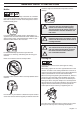
KEY TO SYMBOLS Symbols WARNING! Clearing saws, brushcutters and trimmers can be dangerous! Careless or incorrect use can result in serious or fatal injury to the operator or others. It is extremely important that you read and understand the contents of the operator’s manual. Wear sturdy, non-slip boots. Only use non-metallic, flexible cutting attachments, i.e. trimmer heads with trimmer cord.
CONTENTS Contents KEY TO SYMBOLS Symbols .................................................................... CONTENTS Contents .................................................................... Note the following before starting: ............................. INTRODUCTION Dear customer! .......................................................... WHAT IS WHAT? What is what? ............................................................ GENERAL SAFETY PRECAUTIONS Impor tant ...................................
INTRODUCTION Dear customer! Congratulations on your choice to buy a Husqvarna product! Husqvarna is based on a tradition that dates back to 1689, when the Swedish King Karl XI ordered the construction of a factory on the banks of the Huskvarna River, for production of muskets. The location was logical, since water power was harnessed from the Huskvarna River to create the water-powered plant.
WHAT IS WHAT? LD X What is what? 1 Trimmer head 12 Air purge 2 Bevel gear 13 Fuel tank 3 Grease filler cap, bevel gear 14 Choke control 4 Cutting attachment guard 15 Air filter cover 5 Shaft 16 Handle adjustment 6 Loop handle 17 Drive disc 7 Stop switch 18 Allen key 8 Throttle control 19 Locking pin 9 Throttle lockout 20 Shaft coupling (324LDx) 10 Cylinder cover 21 Operator’s manual 11 Starter handle English – 5
GENERAL SAFETY PRECAUTIONS Important Personal protective equipment IMPORTANT! IMPORTANT! The machine is only designed for trimming grass. A clearing saw, brushcutter or trimmer can be dangerous if used incorrectly or carelessly, and can cause serious or fatal injury to the operator or others. It is extremely important that you read and understand the contents of this operator’s manual.
GENERAL SAFETY PRECAUTIONS CLOTHING Wear clothes made of a strong fabric and avoid loose clothing that can catch on twigs and branches. Always wear heavy, long pants. Do not wear jewellery, shorts sandals or go barefoot. Secure hair so it is above shoulder level. return springs. This arrangement means that the throttle control is automatically locked at the idle setting. FIRST AID KIT Always have a first aid kit nearby.
GENERAL SAFETY PRECAUTIONS then the carburettor idle setting must be checked. See instructions under the heading Maintenance. Vibration damping system Your machine is equipped with a vibration damping system that is designed to reduce vibration and make operation easier. Stop switch Use the stop switch to switch off the engine. Use of incorrectly wound cord or an incorrect cutting attachment increases the level of vibration. See instructions under the heading Cutting equipment.
GENERAL SAFETY PRECAUTIONS Muffler cause the engine to overheat and may lead to serious damage. The muffler is designed to keep noise levels to a minimum and to direct exhaust fumes away from the user. A muffler fitted with a catalytic converter is also designed to reduce harmful exhaust gases. ! In countries that have a warm and dry climate there is a significant risk of fire. We therefore fit certain mufflers with a spark arrestor screen.
GENERAL SAFETY PRECAUTIONS resistance of at least 1.5 Nm. The nut should be replaced after it has been put on approx. 10 times. Trimmer head IMPORTANT! Cutting equipment Always ensure the trimmer cord is wound tightly and evenly around the drum, otherwise the machine will generate harmful vibration. This section describes how to choose and maintain your cutting equipment in order to: • Reduce the risk of blade thrust. • Obtain maximum cutting performance. • Extend the life of cutting equipment.
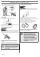
ASSEMBLY Fitting the loop handle • • Before using the unit, tighten the knob securely. Clip the loop handle onto the shaft. Note that the loop handle must be fitted between the arrows on the shaft. Dismantling: • Slide the spacer into the slot in the loop handle. • Fit the nut, knob and screw. Do not overtighten. • Now adjust the trimmer to give a comfortable working position. Tighten the bolt/knob. • Loosen the coupling by turning the knob (at least 3 times). • Push and hold the button (C).
ASSEMBLY Assembling the cutting equipment ! ! ! spanner in the opposite direction to the direction of rotation (Caution! left-hand thread). WARNING! When fitting the cutting attachment it is extremely important that the raised section on the drive disc/support flange engages correctly in the centre hole of the cutting attachment. If the cutting attachment is fitted incorrectly it can result in serious and/or fatal personal injury.
FUEL HANDLING Fuel handling Gasoline Never start the machine: Always use an unleaded quality petrol of at least 90 octane (RON). 1 If you have spilled fuel on it. Wipe off the spillage and allow remaining fuel to evaporate. 2 If you have spilled fuel on yourself or your clothes, change your clothes. Wash any part of your body that has come in contact with fuel. Use soap and water. 3 If the machine is leaking fuel. Check regularly for leaks from the fuel cap and fuel lines.
FUEL HANDLING Oil level Fueling The machine must be switched off and placed on a flat surface when you check the oil level. Unscrew the oil cap, clean the dipstick located on the cap and insert the cap again without screwing it down. Check the oil level on the dipstick. ! WARNING! Taking the following precautions, will lessen the risk of fire: Do not smoke or place hot objects near fuel. Always shut off the engine before refuelling.
STARTING AND STOPPING Check before starting • • Check that the support flange is not cracked due to fatigue or due to being tightened too much. Discard the support flange if it is cracked. Ensure the locking nut has not lost its captive force. The nut lock should have a locking force of at least 1.5 Nm. The tightening torque of the locking nut should be 35-50 Nm.
STARTING AND STOPPING Warm engine Stopping Ignition: Set the stop switch to the start position. Stop the engine by switching off the ignition with the stop button. Choke: Put the choke in working position. Primer bulb: Press the air purge repeatedly until fuel begins to fill the bulb. The bulb need not be completely filled. O ! I L WARNING! When the engine is started with the choke in either the choke or start throttle positions the cutting attachment will start to rotate immediately.
WORKING TECHNIQUES General working instructions 6 Always hold the machine with both hands. Hold the machine on the right side of your body. 7 Keep the cutting attachment below waist level. 8 The engine must be switched off before moving. 9 Never put the machine down with the engine running unless you have it in clear sight. IMPORTANT! This section takes up the basic safety precautions for working with a trimmer.
WORKING TECHNIQUES Basic working techniques Cutting Always slow the engine to idle speed after each working operation. Long periods at full throttle without any load on the engine can lead to serious engine damage. • The trimmer is ideal for cutting grass that is difficult to reach using a normal lawn mower. Keep the cord parallel to the ground when cutting. Avoid pressing the trimmer head against the ground as this can ruin the lawn and damage the tool.
MAINTENANCE Carburetor ! WARNING! The complete clutch cover and shaft must be fitted before the machine is started, otherwise the clutch can come loose and cause personal injury. Function Muffler CAUTION! Some mufflers are fitted with a catalytic converter. See chapter on Technical data to see whether your machine is fitted with a catalytic converter. The muffler is designed to reduce the noise level and to direct the exhaust gases away from the operator.
MAINTENANCE Cooling system Two-piece shaft To keep the working temperature as low as possible the machine is equipped with a cooling system. The drive shaft end in the lower shaft should be lubricated with grease every 30 hours. There is a risk that the drive shaft ends (splined coupling) on models with two-piece shafts will seize if they are not lubricated regularly. Air filter The cooling system consists of: 1 Air intake on the starter. 2 Fins on the flywheel. 3 Cooling fins on the cylinder.
MAINTENANCE Cleaning the air filter Bevel gear Remove the air filter cover and take out the filter. Wash it clean in warm, soapy water. Ensure that the filter is dry before refitting it. The bevel gear is filled with the right quantity of grease at the factory. However, before using the machine you should check that the bevel gear is filled three-quarters full with grease. Use HUSQVARNA special grease. An air filter that has been in use for a long time cannot be cleaned completely.
MAINTENANCE Maintenance schedule The following is a list of the maintenance that must be performed on the machine. Most of the items are described in the Maintenance section. The user must only carry out the maintenance and service work described in this manual. More extensive work must be carried out by an authorised service workshop. Maintenance Daily maintenance Clean the outside of the machine. X Make sure the throttle trigger lock and the throttle function correctly from a safety point of view.
TECHNICAL DATA Technical data 324Lx 324LDx Cylinder displacement, cu.in/cm3 1,53/25,0 1,53/25,0 Cylinder bore, inch/mm 1,38/35 1,38/35 Stroke, inch/mm 1,03/26 1,03/26 Idle speed, rpm 3100 3100 Engine Recommended max. fast idle speed, rpm 11000 11000 Speed of output shaft, rpm 8300 8300 Max. engine output, acc.
TECHNICAL DATA The accessories are recommended for use in combination with the specified power heads and have been evaluated to applicable ISO- and EN safety requirement standards by the Swedish Machinery Testing Institute. Powerhead model 324LDx 324Lx Accessories Art No.
FEDERAL AND CALIFORNIA EMISSIONS CONTROL WARRANTY STATEMENT YOUR WARRANTY RIGHTS AND OBLIGATIONS The EPA (U.S. Environmental Protection Agency), CARB (California Air Resources Board), Environment Canada and Husqvarna Forest & Garden are pleased to explain the emissions control system’s warranty on your 2009 and later small off-road engine. In U.S.
FEDERAL AND CALIFORNIA EMISSIONS CONTROL WARRANTY STATEMENT EMISSION WARRANTY PARTS LIST 1 Carburetor and internal parts 2 Intake pipe, airfilter holder and carburetor bolts. 3 Airfilter and fuelfilter covered up to maintenance schedule. 4 Spark Plug, covered up to maintenance schedule 5 Ignition Module 6 Muffler with catalytic converter 7 Fuel tank WHAT IS NOT COVERED All failures caused by abuse, neglect or improper maintenance are not covered.
Super Auto II Super Auto II 1" 1 2 3 4 2,4 mm .
S35 2 3 2,4-2,7 mm .095-.
S35 3 2 2,4-2,7 mm .095-.
T35, T35x 2 3 2,4-2,7 mm .095-.
1151417-95 ´®z+SIo¶5(¨ ´®z+SIo¶5(¨ 2008-12-22