Operator's manual HUSQVARNA AUTOMOWER® 310/315 Read the operator's manual carefully and make sure that you understand the instructions before you use the product.
Contents 1 Introduction 1.1 Memo..................................................................... 3 1.2 Product description................................................ 3 1.3 Product overview ...................................................6 1.4 Symbols on the product......................................... 7 2 Safety 2.1 Safety definitions....................................................8 2.2 General safety instructions.....................................8 2.
1 Introduction 1.1 Memo Serial number: PIN code: Dealer: Dealer's telephone number: If the robotic lawnmower is stolen, it is important to notify Husqvarna of this. Contact your local Husqvarna representative and provide the robotic lawnmower's serial number so that it can be registered as stolen in an international database. This is an important step in the robotic lawnmower's theft protection which reduces interest in the buying and selling of stolen robotic lawnmowers.
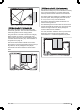
result. The robotic lawnmower can also mow in the rain, however wet grass easily sticks on the robotic lawnmower and there is a greater risk of slipping on steep slopes. hatch is closed again. This together with the START button acts as a start inhibitor. 1.2.4 Movement pattern The movement pattern of the robotic lawnmower is random, which means that a movement pattern is never repeated. With this cutting system the lawn is mown evenly without any mowing lines from the robotic lawnmower.
1.2.5.3 Search method 3 - Follow boundary wire The robotic lawnmower operates irregularly until it reaches the boundary loop. Then it follows the boundary loop to the charging station. The robotic lawnmower randomly selects to travel clockwise or anticlockwise. This search method is suitable in an installation with an open lawn space, wide passages (wider than about 3 m / 10 ft.) and no or only a few small islands. The benefit of this search method is that there is no need to install a guide wire. 1.2.5.
1.3 Product overview 3 2 4 8 10 5 1 9 6 11 7 15 12 19 13 14 21 16 22 17 31 20 18 23 26 29 27 30 32 28 25 24 The numbers in the figure represent: 1. 2. 3. 4. 5. 6. 7. 8. 9. 10. 11. 12. 13. 14. 15. 16. 17.
1.4 Symbols on the product These symbols can be found on the robotic lawnmower. Study them carefully. WARNING: Read the user instructions before operating the robotic lawnmower. WARNING: Operate the disabling device before working on or lifting the machine. The robotic lawnmower can only start when the main switch is set to 1 and the correct PIN code has been entered. Turn the main switch to 0 before carrying out any inspections and/or maintenance.
2 Safety 2.1 Safety definitions 2.2 General safety instructions Warnings, cautions and notes are used to point out specially important parts of the operator's manual. The following system is used in the Operator’s Manual to make it easier to use: WARNING: Used if there is a risk of injury or death for the operator or bystanders if the instructions in the manual are not obeyed.
Warning! Automatic lawnmower! Keep away from the machine! Supervise children! • • Warning! Automatic lawnmower! Keep away from the machine! Supervise children! • • • • • • Use the PARK function or switch off the main switch when persons, especially children or pets, are in the cutting area. It is recommended to program the lawnmower for use during hours when the area is free from activity, e.g. at night. See Timer on page 23.
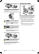
2.3.4 In the event of a thunderstorm 3. Carry the robotic lawnmower by the handle under the robotic lawnmower with the blade disc away from the body. To reduce the risk of damage to electrical components in the robotic lawnmower and its charging station, we recommend that all connections to the charging station are disconnected (power supply, boundary wire and guide wires) if there is a risk of a thunderstorm. CAUTION: Do not lift the robotic lawnmower when it is parked in the charging station.
3 Installation 3.1 Presentation This chapter contains information that is important to be aware of when planning the installation. changed or tampered with. For example the low voltage cable must not be shortened or extended. Before starting the installation make yourself familiar with what is included in the carton.
• • • • Power supply Low voltage cable Screws for the charging station Measurement gauge 3 m / 10 ft 3.2.1 Installation tools During installation you will also need: • • • • Hammer/plastic mallet (to simplify putting the pegs in the ground). Combination pliers for cutting the boundary wire and pressing the connectors together. Polygrip (for pressing the couplers together). Edge cutter/straight spade if the boundary wire must be buried.
The charging station should not be placed on an island as this limits the laying of the guide wire in an optimal way. If the charging station has to be installed on an island, the guide wire also has to be connected to the island. Read more about islands in the Boundaries within the working area on page 16. It is possible to let the low voltage cable cross the working area.
min 30 cm / 12” connected to an electrical socket outdoors, this must be approved for outdoor use. See Connecting the power supply on page 13. 4. Attach the charging station to the ground using the supplied screws. Ensure the screws are screwed all the way down in the countersink. If the charging station is placed against a wall, it is best to wait before securing the charging station to the ground until after all the wires have been connected.
3.5 Boundary wire The boundary wire can be installed in the following ways: • Secure the wire to the ground with pegs. • Staple down the boundary wire if you want to make adjustments to the boundary loop during the first few weeks of operation. After a few weeks the grass will have grown over the wire making it no longer visible. Use a hammer/plastic mallet and pegs. Bury the wire. 10 cm / 4" 0 cm / 0" Bury the boundary wire if you want to dethatch or aerate the lawn.
might be lead to excessive wear on the robotic lawnmower. About 12 cm / 5 in. of the lawn along the ditch/kerbstone will not be mown. robotic lawnmower from ending up outside the working area under any circumstance. min. 15 cm / 6" 30 cm / 12" 1-5 cm / 0.4-2" If the working area borders on a paving stone path or similar that is level with the lawn (+/- 1 cm / 0.4 in.), it is possible to allow the robotic lawnmower to run a little over the path. The boundary wire should then be laid 5 cm / 2 in.
0-15% 0-15 cm / 0-6" 3.5.3.1 Secondary areas If the working area consists of two areas which the robotic lawnmower has difficulty travelling between, it is recommended to set up a secondary area. Instances of this are 40% slopes or a passage that is narrower than 60 cm / 24 in. Lay the boundary wire then around the secondary area so that it forms an island outside of the main area.
• Use a hammer to knock the pegs into the ground. Exercise care when knocking the pegs and make sure the wire is not under strain. Avoid sharp bends. If the boundary wire is to be buried: • 15- cm / 6-" 100 cm / 40" Make sure to lay the boundary wire at a minimum of 1 cm / 0.4 in. and a maximum of 20 cm / 8 in. in the ground. The wire can be buried for instance using an edge cutter or a straight spade. Note: Extra wire must not be placed in coils outside the boundary wire.
1. 2. 2. Press the connectors together using a pair of pliers. Press until you hear a click. 3.5.4.3 Splicing the boundary wire CAUTION: Twinned cables, or a screw terminal block that is insulated with insulation tape are not satisfactory splices. Soil moisture will cause the wire to oxidise and after a time result in a broken circuit. 3. Cut off any surplus boundary wire. Cut 1-2 cm / 0.4-0.8 in. above each connector.
2. 3. 4. The robotic lawnmower runs at varying distances from the guide wire to reduce the risk of tracks forming. The area beside the wire which the robotic lawnmower then uses is called the Corridor. The wider the corridor allowed by the installation, the less the risk of tracks forming. The robotic lawnmower always runs to the left of the guide wire as seen facing the charging station. Thus the corridor is to the left of the guide wire.
easier if an eyelet has been made on the boundary wire as outlined in the previous description. See Laying the boundary wire on page 18. 3.8 Checking the installation Check the loop signal by inspecting the indicator lamp on the charging station. See Indicator lamp in the charging station on page 52 if the lamp does not indicate a solid or flashing green light. 3.9 First start-up and calibration 8.
3.11 Control panel 3.11.1 Instruction - Control panel All commands and settings for the robotic lawnmower are made via the control panel. All functions are accessed via a number of menus. The control panel consists of a display and a keypad. All information is shown on the display and all input is done using the buttons. The battery status shows the remaining battery charge. If the robotic lawnmower is loading, a flash is also shown over the battery symbol (D).
Settings This selection allows you to make changes to the general robotic lawnmower settings such as date and time. You can also turn on/off ECO mode and Spiral cutting, or save your settings in different Profiles (Automower 315 only). See Settings on page 31. 3.12.1 Main menu Accessories Timer This menu handles the settings for robotic lawnmower accessories, for examples Automower Connect.
days a week. This is normally a suitable setting for a working area corresponding to the maximum capacity, see Technical data on page 58. • • If the working area is less than maximum capacity then the timer should be used to minimize wear on grass and lawnmower. When setting the timer, calculate that the robotic lawnmower mows about the number of square meters per hour and day listed in table Work capacity. See To set the timer on page 43. • • Find a work area that closest matches the size of the lawn.
3.13.4 Copy Use this function to copy the current day settings to other days. Mark Copy by using arrow keys and press OK. Then use the up and down arrow keys to move the cursor between days. The times will be copied to the days that are marked with OK. Low and Medium security prohibits access to the robotic lawnmower if the PIN code is unknown. High security also includes a warning that beeps if the correct PIN code is not entered after a designated time period.
3.14.2.2 Change PIN code Enter the new PIN code and press OK. Confirm by entering the same code again and pressing OK. When the PIN code is changed, the message PIN code changed appears in the display. Make a note of the new PIN code on the designated line in Memo. See Memo on page 3. 3.14.2.3 Duration 3.15.2 Info messages Messages shown in the display not caused by an actual fault are instead saved under the Info messages heading. Examples for such messages is Slope too steep.
2. Use the right and left arrow keys to increase or decrease the cutting time in 3 preset intervals. Lawn coverage 3.17 Installation For many working areas there is no need to change the factory settings but sometimes, depending on the lawn complexity, the mowing result can be improved by making manual settings. Area 1, 2 or 3 How? How far? How often? Disable More INSTALLATION Lawn coverage The factory settings allow the robotic lawnmower to follow the guide wire 300 m / 984 ft.
3.17.1.6 Test: Area 1, 2 or 3 To test the selected settings: ? m / ft. 3.17.1.3 Area 1, 2 or 3 > How often? How often the robotic lawnmower must be steered to the remote area is selected as a proportion of the total number of times it leaves the charging station. At all other times, the robotic lawnmower starts to mow at the charging station. Select the percentage that corresponds to the size of the remote area relative to the total working area.
irregularly for 3 minutes and then searches for the guide wires for 8 minutes. If it has not found a guide wire after this period, the robotic lawnmower now also searches for the boundary loop. It is possible of course to specify the same delay time for both the guide wires and boundary loop, for instance 5 minutes.
only if the robotic lawnmower is able to follow the guide wire the entire distance to the charging station and docks at the first attempt. If the robotic lawnmower is unable to dock on the first attempt, it will automatically try again. The installation is not approved if the robotic lawnmower needs two or more attempts to dock with the charging station.
The factory settings can be used for many working areas, i.e. the robotic lawnmower itself can use the inbuilt functions to operate in the widest possible corridor. In more complex gardens e.g. where the guide wire is placed close to obstacles which cannot be isolated using the boundary loop, operational safety can be improved by carrying out some of the manual settings outlined below. 3.17.3.2 Corridor width > Boundary The boundary corridor width is specified in intervals from 1-9.
3.18.1.3 Change the name of a Profile The names of the profiles can be changed, to make it easier to remember what settings are stored in the respective profile. SETTINGS Profiles ECO mode Spiral cutting General 3.18.1 Profiles With the function Profiles, different sets of user settings can be saved. Up to 3 different profiles can be stored. The unique connection between the mower and the charging station is saved in the profiles.
ECO mode the robotic lawnmower otherwise can not be started inside the working area. 3.18.4.1 Time & Date This function allows you to set current time and date and required formats. 3.18.3 Spiral cutting If the robotic lawnmower enters an area where it senses the grass is longer than average, it can change the movement pattern. It can then mow in a spiral pattern to faster cut the area of longer grass.
The SIM symbol indicates there is a problem with the SIM card or the module. Make sure the SIM card support 2G data communication, that there is sufficient funds on the card (applies to pre-paid SIM cards) and that the APN settings agree. ACCESSORIES Information Automower Connect Mower house 3.19.2.2 Main menu The main menu in Automower Connect consists of: 3.19.1 Information • This menu handles accessories mounted on the mower.
When putting the robotic lawnmower into storage for a long period, such as during the winter, we recommend turning off the main switch. With the GeoFence function activated, you will need the PIN code in order to turn off the robotic lawnmower. Once the main switch has been turned off, the Connect function will stay active for another 12 hours. After that it will not be possible to communicate with the robotic lawnmower and the GeoFence function will not be active. 3.19.2.
3.
3.
3.22 Yard layout examples The robotic mower’s behaviour is controlled to a certain extent by what settings are made. Adapting the robotic lawnmower's settings according to the shape of the lawn makes it easier for the robotic lawnmower to frequently reach all parts and therefore achieve a perfect mowing result. Different layouts require different settings. The following pages outline a number of layout examples with installation proposals and settings.
3.22.3 L-shaped garden with a couple of islands and the charging station installed in the narrow area Area 800 m2 / 8611 sq. ft.
3.22.5 Unsymmetrical working area with a narrow passage and a number of islands Area 800 m2 / 8611 sq. ft. Timer Automower 310 07:00 am - 12:00 am, Monday to Saturday Automower 315 08:00 am - 10:00 pm, Monday to Saturday Lawn coverage 2 m / 7 ft Factory setting Find charging sta- Factory setting tion Remarks The guide wire must be placed along the narrow passage to ensure that the robotic lawnmower can with ease locate the charging station from the right hand side of the working area.
3.22.7 A secondary area Area 500 + 100 m2 / 5382 + 1076 sq. ft. Timer Automower 310: 08:00 am - 08:30 pm, Monday, Tuesday, Thursday, Friday, Saturday Automower 315: 08:00 am - 06:30 pm, Monday, Tuesday, Thursday, Friday, Saturday Lawn coverage Factory setting Find charging sta- Factory setting tion Remarks The secondary area is cut using the Secondary area mode on Wednesday and Sunday. As the area is open and uncomplicated there is no need for a guide wire in this installation.
4 Operation 4.1 Main switch WARNING: Read the safety instructions carefully before you start your robotic lawnmower. Note: Always press the START button before closing the hatch to start the robotic lawnmower. If the START button is not pressed, a message beep is heard and the robotic lawnmower will not start. Before the blade disc starts a warning beep can be heard consisting of 5 short beeps for 2 seconds. WARNING: Keep your hands and feet away from the rotating blades.
pressing right arrow key and then specifying On Main area or On Secondary area. 4.4 Operating mode Park When the PARK button is pressed the following operation selections can be chosen. Always switch the robotic lawnmower off using the main switch if it requires maintenance or if the robotic lawnmower must be moved outside the working area. 4.7 Timer and Standby Use the timer function (see Timer on page 23 ) to avoid a downtrodden lawn. 4.7.
4.8 Charge a flat battery 24 h When the Husqvarna robotic lawnmower is new or has been stored for a long period, the battery will be flat and needs to be charged before starting. A M Ch owing arg in g WARNING: Only charge the robotic lawnmower using a charging station which is intended for it. Incorrect use may result in electric shock, overheating or leakage of corrosive liquid from the battery.
MAX to avoid damaging the loop wire. After this, the cutting height can be lowered step by step every week until the desired cutting height has been reached.
5 Maintenance 5.1 Introduction - maintenance For better operating reliability and longer service life: check and clean the robotic lawnmower regularly and replace worn parts if necessary. All maintenance and servicing must be done according to Husqvarna's instructions. See Guarantee terms on page 60. When the robotic lawnmower is first used, the blade disc and blades should be inspected once a week. If the amount of wear during this period has been low, the inspection interval can be increased. 5.2.
batteries. Do not use non-rechargeable batteries. CAUTION: The battery must be charged fully before winter storage. If the battery is not fully charged it can be damaged and in certain cases be rendered useless. 5.3.1 To replace the blades 1. Set the main switch to position 0. If the operating times for the robotic lawnmower are shorter than normal between charges, this indicates that the battery is getting old and eventually needs replacing.
6 Troubleshooting 6.1 Introduction - troubleshooting In this chapter, a number of messages are listed which may be shown in the display if there is a malfunction. There is a proposal as to the cause and steps to take for each message. This chapter also presents some symptoms that can guide you if the robotic lawnmower does not work as expected. More suggestions for steps to take in the event of malfunction or symptoms can be found on www.husqvarna.com. 6.
Message Cause Outside working area The boundary wire connections to the charging station are crossed. Action Check that the boundary wire is connected correctly. The boundary wire is too close to the edge of Check that the boundary wire has been laid the working area. according to the instructions. See Installation on page 27. The working area slopes too much by the boundary loop. The boundary wire is laid in the wrong direction around an island.
Message Cause Action Stuck in charging sta- There is an object in the way of the robotic tion lawnmower preventing it from leaving the charging station. Remove the object. Upside down Turn the robotic lawnmower the right way up. The robotic lawnmower is leaning too much or has turned over. Needs manual charg- The robotic lawnmower is set to the Seconing dary area operating mode. Place the robotic lawnmower in the charging station. This behaviour is normal and no action is required.
Message Cause Action Connectivity problem Potential problem on the connectivity circuit board in the mower. Restart the mower. If the problem remains, the message requires action by authorized service technician. Connectivity settings restored The connectivity settings was restored due to Please check and change the settings if neea fault. ded. Poor signal quality The connectivity circuit board in the mower is Verify the mower is not upside down or tilted.
6.4 Indicator lamp in the charging station For a fully functional installation, the indicator lamp in the charging station must emit a solid or flashing green light. If something else appears, follow the troubleshooting guide below. There is more help on www.husqvarna.com. If you still need help, please contact your local Husqvarna representative. Light Cause Action Solid green light Good signals No action required Green flashing light The signals are good and ECO mode is activated.
Symptoms Cause Action The robotic lawnmow- The robotic lawnmower searches for the er runs, but the blade charging station. disc does not rotate. No action. The blade disc does not rotate when the robotic lawnmower is searching for the charging station. The robotic lawnmow- Grass or other foreign object blocks the blade Remove and clean the blade disc. See Clean er mows for shorter disc. the robotic lawnmower on page 46. periods than usual The battery is spent. Replace the battery.
a) If the suspected boundary wire is short then it is easiest to exchange all of the boundary wire between AL and the point where the guide wire is connected to the boundary wire (thick black line). 2. Check that the boundary wire connections to the charging station are properly connected and not damaged. Check that the indicator lamp in the charging station is still flashing blue.
Continue until only a very short section of the wire remains which is the difference between a solid green light and a flashing blue light. Then follow instruction in step 5 below. 4. If indicator lamp still flashes blue in step 3 above: Put AL and G1 back in their original positions. Then switch AR and G1. If indicator lamp now is lit with a solid green light then disconnect AL and connect a new boundary wire to AL. Connect the other end of this new wire at the middle of the suspected wire section.
7 Transportation, storage and disposal 7.1 Transportation The contained lithium-ion-batteries are subject to the Dangerous Goods Legislation requirements. For commercial transports e.g. by third parties or forwarding agents, special requirement on packaging and labeling must be observed. Consult an expert for hazardous material for preparation of the item being shipped. Please also observe possibly more detailed national regulations.
5. Loosen all 14 screws (Torx 20). 6. Remove the guarantee seal at the point of separation between the chassis halves on the righthand side. 7. Carefully lift the rear edge of the upper section of the chassis. 8. Disconnect the MMI cable from the main circuit board and remove the upper section of the chassis. 9. Loosen the 3 screws (Torx 20) holding the battery cover in place. 10. Disconnect the battery connection from the main circuit board. Open the battery cover and remove the battery.
8 Technical data 8.1 Technical data Dimensions Automower 310 Automower 315 Length, cm 63 63 Width, cm 51 51 Height, cm 25 25 Weight, kg 8.5 8.5 Electrical system Automower 310 Automower 315 Battery, Lithium-Ion 18 V/2.1 Ah Art.
Mowing Automower 310 Automower 315 Maximum length boundary wire, m 800 800 Maximum length guide wire, m 400 400 1000 1500 IP-classification Automower 310 Automower 315 Robotic lawnmower IPX4 IPX4 Charging station IPX1 IPX1 Power supply IPX4 IPX4 Working capacity, m2+/- 20% Husqvarna AB does not guarantee full compatibility between the robotic lawnmower and other types of wireless systems such as remote controls, radio transmitters, hearing loops, underground electric animal fencing
9 Warranty 9.1 Guarantee terms Husqvarna guarantees this product’s functionality for a period of two years (from date of purchase). The guarantee covers serious faults relating to materials or manufacturing faults. Within the guarantee period, we will replace the product or repair it at no charge if the following terms are met: • • The robotic lawnmower and the charging station may only be used in compliance with the instructions in this Operator’s Manual.
10 EC Declaration of Conformity 10.1 EC Declaration of Conformity Husqvarna AB, SE-561 82 Huskvarna, Sweden, tel: +46-36-146500, declares that the Robotic lawnmovers Husqvarna Automower® 310 and Husqvarna Automower® 315 with serial numbers dating 2017 week 10 and onwards (the year and week is clearly stated on the rating plate, followed by the serial number), comply with the requirements of the COUNCIL’S DIRECTIVE: • Directive “relating to machinery” 2006/42/EC.
- EC Declaration of Conformity 473 - 001 -
473 - 001 - EC Declaration of Conformity - 63
AUTOMOWER® is a trademark owned by Husqvarna AB. Copyright © 2017 HUSQVARNA. All rights reserved. www.husqvarna.