
Use and Care Guide


1.3 Product overview
1
12
13
14
2
3
4
5
6
9
8
11
15
10
1816
17
22
20
19
21
25
26
27
23
28
29
30
31
32
7
24
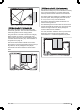
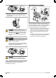
The numbers in the figure represent:
1. Body
2. Hatch to cutting height adjustment
3. Hatch to display and keypad
4. Stop button
5. Replaceable cover
6. Rear wheels
7. Front wheels
8. Cutting height adjustment
9. Contact strips
10. LED for operation check of the charging station and
boundary wire
11. Charging station
12. Rating plate
13. Display
14. Keypad
15. Cutting system
16. Chassis box with electronics, battery and motors
17. Handle
18. Main switch
19. Blade disc
20. Skid plate
21. Power supply (the appearance of the power supply
may differ depending on market)
22. Loop wire for boundary loop and guide wire
1
23. Couplers for loop wire
2
24. Pegs
3
25. Connector for the loop wire
4
26. Screws for securing the charging station
27. Measurement gauge for help when installing the
boundary wire (the measurement gauge is broken
loose from the box)
28. Operator’s Manual and Quick Guide
29. Cable markers
30. Extra blades
31. Low voltage cable
32. Alarm decal
1
Is a part of the Installation kit which is purchased separately.
2
See note 1
3
See note 1
4
See note 1
6 - Introduction 473 - 001 -