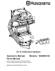
Z1-9 Collection System Operators Manual Parts Manual Models: 968999196 Please read these instructions carefully and make sure you understand them before using the machine. MANUAL NO. 540200896 REV.
INDEX Operators Guide Specifications ............................................................................................ 3 Features and Controls ............................................................................... 4 General Information ................................................................................... 5 Safety Procedures ..................................................................................... 5 Unpacking Instructions .........................................
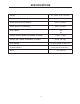
SPECIFICATIONS Height 47 - 50 in. (119 - 127 cm.) Length 38 in. (97 cm.) Width (without hose or blower) 34.5 in. (94 cm.) Width (with hose and blower) 49 in. (124 cm.) Deck Options 42” 48” Weight (without spindle drive/blower assembly) 170 lb. (77 kg.) Weight (with spindle drive/blower assembly) 235 lb. (107 kg.) 11.5 cu ft (9.2 bu. or 0.33 m3) Total Capacity 8 cu ft (6.4 bu. or 0.23m3) Usable Capacity Hose 7 in. (18 cm.
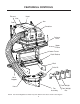
FEATURES & CONTROLS Exhaust Hood Inlet Arm Door Container Release Lever Upper Frame Lower Frame Hitch Bracket Hitch Drive Kit Hose Support Front Weight Hose Fan Assembly Front Weight Bar NOTE: Your Front Weight Bar and Hitch may look different from those shown in this diagram.
SAFETY RULES Safety Procedures General Information This manual will assist you in the safe operation and proper maintenance of your Husqvarna 1 - Training: equipment. Read it thoroughly before attempting • Read the Operator’s manual. If the operator(s) or mechanic(s) can not read English it is the to operate the machine. Call your dealer or owner’s responsibility to explain this material to Husqvarna Customer Service if additional them. information is required.
SAFETY RULES 3 - Operation • Never run an engine in an enclosed area. • Only operate in good light, keeping away from holes and hidden hazards. • Slow down and use extra care on hillsides. Make turns gradually and at slow speed. Do not operate across the sides of slopes. Operate up and down slopes only. Do not operate on steep slopes. • Turf conditions can affect the machine’s stability. Do not operate on wet grass where traction may be reduced.
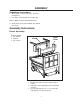
ASSEMBLY Unpacking Instructions 1. Wear gloves and eye protection. Remove wood pieces. 2. Cut straps around carton and remove top. NOTE: Watch for nails and wood splinters. 3. Slide carton sleeve out of bottom tray and lift over Z1-9. Assembly Instructions Frame Assembly Tools Required: 1. 3/4" wrench 2. Ratchet 3. 3/4" socket Lower Frame Upper Frame 1. Position the Lower Frame inside the Upper Frame. 2. Align holes corresponding to desired position of frame. 3.
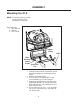
ASSEMBLY Mounting the Z1-9 NOTE: This portion of the assembly requires lifting the Z1-9; two people are required. Tools Required: 1. 9/16" wrench 2. Ratchet 3. 9/16" socket Upper Frame Hitch Hitch Bracket Lower Frame Wire Lock Pin 1. Install the Hitch from the Custom Kit according to the instruction sheet included in that carton. 2. Slide the Z1-9 into the hitch. 3. Line up holes in the Hitch and Z1-9 and secure with two (2) 3/8” wire lock pins. 4.
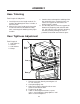
ASSEMBLY Spindle Drive & Drive Kit Assembly For use on mowers equipped with 42", 48", 52" or 61" decks: 12. Rest the fan assembly onto the deck end and slide the pilot thru the 5/8” hole previously mentioned so that fan assembly is supported by the pilot and the ¼” stop block welded under the clamp at the front of the fan assembly. Note: It may be necessary to swing the idler pulley away from the assembly mounting face to clear the chute mounting bar and the discharge chute mounting tab on the deck. 13.
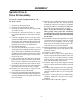
ASSEMBLY Hose Trimming Tools Required: Utility Knife 3 Continue that cut through the webbing all the way around the hose so that it finishes just across the support coil from where the original cut was started. 4. Use the utility knife to score the support coil between the beginning and end of the web cut. Set aside the knife, and finish breaking the coil by hand by working the scored portion back and forth until it breaks apart. 1. Carefully measure the length needed.
OPERATION Operating the Vacuum 1. NEVER USE THE Z1-9 WITHOUT ALL HOSES AND SHIELDS SECURELY ATTACHED. 2. Make sure all hoses are connected at both ends. Inspect hoses prior to each use. 3. Do not use the Z1-9 on slopes greater than 15 degrees. 4. The mower must be running in order to vacuum debris through the mower deck. 5. In heavy grass it may be necessary to mow and vacuum at a slower ground speed. 6.
SERVICE AND MAINTENANCE Transport WARNING The Z1-9 container must be completely empty while driving forward onto a trailer. If the Z1-9 must be loaded onto a trailer while there is still debris in the container, the mower must be backed up onto the trailer to avoid tipping. For best results, clean exhaust screen inside container regularly. Instructions for doing this can be found in the Service section of this manual. Storage Cleaning and Washing 1.
SERVICE AND MAINTENANCE Caring For Vacuum Hoses Cleaning Exhaust Screen 1. Inspect hoses before each use. If hoses have excessive wear, tears, or punctures, replace immediately. 2. To prolong the life of the hose, periodically rotate hose and turn hose end to end. Refer to Preventative Maintenance Schedule in this manual. 3. Avoid twists and sharp turns in the hoses, as they will increase wear on the hoses. 4. Avoid dragging the lower hose along the sides of buildings or other hard surfaces.
SERVICE AND MAINTENANCE Trouble Shooting Guide DANGER Before servicing unit, wait for all moving parts to come to a complete stop. Turn engine off and remove the spark plug wire. PROBLEM Engine Does Not Start. POSSIBLE CAUSE 1. Spark plug wire disconnected. 2. Engine ON/OFF switch in OFF position. 3. Fuel tank empty. 4. Stale gasoline. 5. Dirty air filter. Engine Runs Poorly. 1. Bad spark plug. 2. Dirty air filter. 3. Incorrect choke setting. 4. Stale gasoline. CORRECTION 1. Reconnect wire. 2.
PARTS ILLUSTRATION 15
CONTAINER ASSEMBLY 27 26 2 24 16 28 1 11 4 6 7 8 3 12 18 13 15 4 12 17 25 8 17 10 9 23 14 7 5 19 20 21 17 16 22
CONTAINER ASSEMBLY ITEM PART NO. QTY DESCRIPTION 1 ......... 539108970 ....... 1 .......... CONTAINER ASM. 2 ......... 540200873 ....... 1 .......... EXHAUST ASM. 3 ......... 540200691 ....... 2 .......... CLEVIS PIN, 1/4 X 2 3/4 4 ......... 540099082 ....... 4 .......... HAIR PIN, #13 5 ......... 540200872 ....... 1 .......... DOOR ASM. 6 ......... 540200692 ....... 2 .......... CLEVIS PIN, 3/8 X 1 3/4 7 ......... 540030425 ....... 4 .......... ROD END 8 ......... 540200690 ....... 4 .......... PLUG 9 ...
FRAME ASSEMBLY 19 17 18 16 14 11 15 9 8 2 12 10 7 3 13 11 6 5 4 6 1 20 7 ITEM PART NO. QTY DESCRIPTION 1 ......... 540062072 ....... 1 .......... LOWER FRAME 2 ......... 540200510 ....... 1 .......... UPPER FRAME 3 ......... 540099069 ....... 8 .......... BOLT, 1/2-13 X 1 1/4 4 ......... 540099020 ....... 4 .......... BOLT, 3/8-16 X 1 1/4 5 ......... 540093082 ....... 8 .......... NUT, 1/2-13, NYLOC 6 ......... 540000415 ....... 8 .......... WASHER, 3/8 7 ......... 540099065 ....... 4 ......
HITCH & FRONT WEIGHT BAR ASSEMBLY 540200809 540092731 540099668 540200932 540092531 FRONT WEIGHT QTY 2 INCLUDED WITH COLLECTION UNIT QTY 1 INCLUDED WITH CUSTOM KIT SEE INSTRUCTION SHEET INCLUDED WITH CUSTOM KIT FOR PARTS LIST.
SPINDLE DRIVE ASSEMBLY 19 5 22 28 21 23 7 1 20 6 27 24 39 2 23 14 27 21 4 10 40 9 46 36 42 37 35 25 11 33 14 18 34 31 32 13 26 30 28 29 44 8 46 45 43 8 12 15 41 17 15 16 27 28 29 28 29 3 20 38
SPINDLE DRIVE ASSEMBLY ITEM PART NO. QTY DESCRIPTION 1 ......... (539) 106752 .... 1 .......... FAN COVER W/DECALS 2 ......... (539) 108941 .... 1 .......... UPPER HOUSING 3 ......... (539) 109900 .... 1 .......... LOWER HOUSING 4 ......... (539) 106786 .... 2 .......... BEARING W/O COLLAR 5 ......... (539) 106786 .... 1 .......... LOCKING COLLAR 6 ......... (539) 106707 .... 1 .......... FAN WLDMT. 7 ......... (539) 102691 .... 5 .......... FLANGETTE 8 ......... (539) 108944 .... 2 ..........
DRIVE KIT ASSEMBLY (539) 108960 - 42 INCH DECK (539) 108961 - 48 INCH DECK (539) 108962 - 52 INCH DECK (539) 108963 - 61 INCH DECK 1 8 3 4 2 5 6 7 ITEM PART NO. QTY DESCRIPTION 1 ......... (539) 108950 .... 1 .......... 42 SHIELD ........... (539) 108953 .... 1 .......... 48 SHIELD ........... (539) 108958 .... 1 .......... 52 SHIELD ........... (539) 108959 .... 1 .......... 61 SHIELD 2* ........ (539) 106739 .... 1 .......... SPACER 3 ......... (539) 976998 .... 1 .......... ZERK 4 .........