
Product Manual

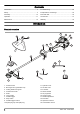


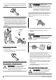
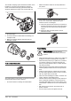

Table Of Contents
- Contents
- Introduction
- Safety
- Assembly
- Operation
- Maintenance
- Troubleshooting
- Transportation and storage
- Technical data
- Accessories
- Warranty
- Contenido
- Introducción
- Seguridad
- Montaje
- Funcionamiento
- Mantenimiento
- Solución de problemas
- Transporte y almacenamiento
- Datos técnicos
- Accesorios
- Garantía
- Table des matières
- Introduction
- Sécurité
- Montage
- Fonctionnement
- Entretien
- Dépannage
- Transport et entreposage
- Caractéristiques techniques
- Accessoires
- Garantie

• Always stop the engine and let it cool off for a few
minutes before you refuel.
• Open the fuel cap slowly so that any excess
pressure is released gently when you refuel.
• Tighten the fuel cap carefully after you refueled.
• Clean the area around the fuel cap. Contamination in
the tank can cause operating problems.
• Always move the product 3m (10ft) or further from
the refuelling area and source before starting.
Safety instructions for maintenance
WARNING: Always stop the engine
before you do any work on the cutting
attachment. The cutting attachment
continues to rotate even after the throttle
has been released. Ensure that the cutting
attachment has stopped completely and
disconnect the spark plug before you start to
work on it.
WARNING: A faulty cutting attachment
may increase the risk of accidents.
WARNING: Make sure that the trimmer
cord is wound tightly and evenly around the
drum, otherwise the product will generate
harmful vibration.
• Only use cutting attachments with the guards we
recommend. Refer to
Accessories on page 21
.
• Your warranty may not cover damage or liability
caused by the use of non-authorized accessories or
replacement parts.
Assembly
Introduction
WARNING: Before you assemble the
product, you must read and understand the
safety chapter.
WARNING: Remove the spark plug
cable from the spark plug before you
assemble the product.
To assemble the loop handle
1. Attach the loop handle onto the shaft between the
arrow symbols.
2. Put the bracket on the opposite side and put the 2
screws into the holes on the loop handle.
3. Adjust the loop handle to a comfortable position.
4. Tighten the screws.
To assemble and disassemble the cutting
attachment guard and trimmer head
1. Attach the correct cutting attachment guard (A) for
the trimmer head. Refer to
Accessories on page 21
.
2. Put the cutting attachment guard onto the fitting on
the shaft.
3. Attach the cutting attachment guard with the screws
(B).
4. Install the drive disc (C) on the output shaft.
5. Turn the output shaft until one of the holes in the
drive disc aligns with the related hole in the gear
housing.
6. Put the locking pin (D) in the hole to lock the shaft.
A
D
C
B
7. Turn the cutting equipment (E) in the opposite
direction from which the cutting equipment rotates.
E
E
10 1560 - 002 - 22.06.2021