English Operator Manual Z 248F / 97045890100 Please read the operator manual carefully and make sure you understand the instructions before using the machine. Gasoline containing a maximum of 10% ethanol (E10) is permitted for use in this machine. The use of gasoline with more than 10% ethanol (E10) will void the product warranty.
CONFORMITY CERTIFICATES USA requirements Labels are placed on the engine and/or in the engine compartment stating that the machine will fulfil the requirements. This is also applicable to special requirements for any of the states, (California emission rules etc.). Do not remove these labels. Certificates can also be supplied with the machine at delivery or written in the Engine manual. Take care of them as they are valuable documents.
CONTENTS INTRODUCTION....................................................... 4 Driving and Transport on Public Roads................ 4 Towing................................................................... 4 Operating.............................................................. 4 SYMBOLS AND DECALS......................................... 6 SAFETY..................................................................... 7 Protecting Children...............................................
INTRODUCTION Congratulations Thank you for purchasing a Husqvarna rideon mower. This machine is built for superior efficiency to quickly mow primarily large areas. A control panel that the operator can easily access and a hydrostatic transmission regulated by steering controls each contribute to the machine’s performance. This manual is a valuable document. Read the contents carefully before using or servicing the machine.
INTRODUCTION Good Service Husqvarna’s products are sold around the world at independent dealers, retailers and online stores. No matter where you buy a Husqvarna product or solution, you can count on our team to provide you with dedicated service and support throughout the life of the product.
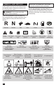
SYMBOLS AND DECALS These symbols are found on the machine and in the operator manual. Study them carefully until you know what they mean. WARNING! Xxxx xxxxxx xxxxx xxxx xxxxxxxxx xxxxxx xxxxxxxxx. IMPORTANT INFORMATION Xxxx xxxxxx xxxxx xxxx xxxxxxxxx xxxxxx xxxxxxxxx. Used in this publication to tell the reader of a risk of material damage, particularly if the reader neglects to obey the instructions in the manual. Used also when there is a possibility for misuse or misassembly.
SAFETY Safety Instructions These instructions are for your safety. Read them carefully. WARNING! THIS CUTTING MACHINE CAN AMPUTATE HANDS AND FEET AND THROW OBJECTS. FAILURE TO OBEY THE FOLLOWING SAFETY INSTRUCTIONS COULD CAUSE SERIOUS INJURY OR DEATH. WARNING! CHILDREN CAN BE SERIOUSLY INJURED OR KILLED BY THIS EQUIPMENT. Carefully read and obey all the safety instruction that follow.
SAFETY • Disengage blades when not mowing. Shut off engine and wait for all parts to come to a full stop before cleaning the machine, removing the grass catcher or unclogging the discharge guard. • Do not operate the machine while under the influence of alcohol or drugs. • Look for traffic when operating near or going across roadways. • Use more care when loading or removing the machine into a trailer or truck. • Always wear eye protection when operating machine.
SAFETY Safe Handling of Gasoline To avoid personal injury or damage to property, use care in handling gasoline. Gasoline is very flammable and the fumes are explosive. WARNING! The engine and the exhaust system become very hot during operation. There is a risk for burns if touched. Let engine and exhaust system to cool before refueling. • Do not fuel the machine indoors. • Extinguish all cigarettes, cigars, pipes, and other sources of ignition. • Use only approved gasoline containers.
SAFETY • Make sure that the fuel filler cap is mounted tightly and no flammable substances are kept in an open vessel. • Sparking can occur when working with the battery and the heavy cables of the starter circuit. This can cause battery explosion, fire or eye injury. Sparking will not occur after the grounding cable (normally negative, black) is removed from the battery. • Disconnect the grounding cable from the battery first and reconnect it last.
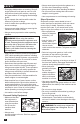
Transmission from the engine is made via belt-driven hydraulic pumps. Using the left and right steering controls, the flow is regulated and thereby the direction and speed. CONTROLS This operator manual describes the Husqvarna Zero Turn Rider. The rider is fitted with a fourstroke overhead valve engine. 5 6 7 4 8 9 3 10 11 12 2 1 1. Steering / park brake controls 5. Bypass Linkages 9. Throttle control 2. Tracking bolt, left 6. Fuel shut off valve 10. Service meter 3. Deck lift 7.
Park Brake CONTROLS Steering Control Levers The machine’s speed and direction are continuously variable using the two steering controls. The steering controls can be moved forward or rearward around a neutral position. There is a neutral position, which is locked if the steering controls are moved out. When the two controls are in the neutral position (N), the machine stands still. By equally moving the controls forward or rearward, the machine moves in a straight line forward or rearward.
CONTROLS Service Meter Choke control The choke control is used for cold starts to supply the engine with a richer fuel mixture. For cold starts the control should be pulled up. Ignition Switch The service meter displays the total number of hours the engine has run and indicates when the engine and mower need servicing. After every 50 hours of operation, an oil can icon will appear and stay on for two hours, before an automatic reset occurs.
CONTROLS Cutting Height Lever Fuse The 20 amp primary fuse is located on the left hand side of the machine. It is accessed by tilting the seat forward. The fuse is a flat pin type used in automobiles. Bypass Linkages To set the deck cutting height, pull the cutting height lever in and move it to the correct height notch. IMPORTANT INFORMATION Always raise the deck to the highest position for transport.
CONTROLS Fuel Tank IMPORTANT INFORMATION Experience shows that alcohol blended fuels (called gasohol, ethanol or methanol) can attract moisture which leads to separation and formation of acids during storage. Acidic gas can damage the fuel system of an engine while in storage. To avoid engine problems, the fuel system should be emptied before storage of 30 days or longer. Drain the gas tank, start the engine and let it operate until the fuel lines and carburettor are empty. Use new fuel the next season.
OPERATION Read the Safety section and following pages, if you are unfamiliar with the machine. Training Due to unique steering capabilities, zero turn mowers are far more maneuverable than typical riding mowers. Review this section fully before trying to move the mower under its own power. When first operating the mower or until becoming comfortable with controls, use a reduced throttle speed and reduced ground speed.
OPERATION 3. Disengage the mower blades by pushing the blade switch down. 4. Move the steering / park brake controls firmly out to the locked position. 5. Move the throttle lever to the middle throttle position. If the engine is cold, the choke control should be pulled up. 2. Lower the mower deck to the correct cutting height. 3. Move throttle control to full throttle (rabbit symbol). 4. Engage the mower deck by pulling the blade switch up.
OPERATION Operating on Hills Read the Safety Instructions Driving on Slopes in the Safety section. • Use the slowest speed possible before starting up or down hills. • Try not to stop or change speed on hills. • If stopping is fully necessary, pull steering / park brake controls into the neutral position and push outward to engage the park brake. • Pull the steering / park brake controls back to the center of the mower and push forward to regain forward movement. • Make all turns slowly.
OPERATION 4. To re-engage the EZT’s to drive, reverse the above procedure. Load the machine into truck or trailer by driving slowly up the ramps. DO NOT LIFT! The machine is not intended to be lifted by hand. • • WARNING! Make no adjustments without: the engine stopped, the park brake engaged WARNING! Bypass linkages are located near to the muffler. To prevent burns, the engine should be shut off and allowed to cool before the bypass linkage levers are touched.
carried out by an authorized service workshop is recommended to maintain your machine in the best possible condition and to make sure of safe operation. Read General Maintenance in the Safety section. MAINTENANCE Maintenance Schedule Following is a list of maintenance procedures that must be performed on the machine. For those points not described in this manual, visit an authorized service workshop.
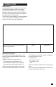
MAINTENANCE DAILY BEFORE MAINTENANCE AFTER AT LEAST ONCE EACH YEAR MAINTENANCE INTERVAL IN HOURS 25 CHECK Throttle cable for adjustment Mower deck for adjustment Condition of belts, belt pulleys Caster wheels (at 200 hour intervals) Engine valve clearance 3) CHANGE Spark plugs Engine oil 1) Engine oil filter Fuel filter Paper air filter 2) Air cleaner foam pre-filter 2) 4) Air cleaner paper filter cartridge 2) ALSO Do the 300-hour service 3) ● ♦ ■ = Described in this manual = Not described in this
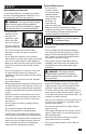
MAINTENANCE Battery If the battery is too weak to start the engine, it must be recharged. Jumper Cable Use 1. Connect each end of the RED cable to the POSITIVE (+) terminal on each battery, taking care not to short against chassis. 2. Connect one end of the BLACK cable to the NEGATIVE (-) terminal of the fully charged battery. 3. Connect the other end of the BLACK cable to a good CHASSIS GROUND on the mower with the discharged battery, away from the fuel tank and battery. To remove cables, reverse order 1.
MAINTENANCE Safety System The machine is equipped with a safety system that prevents starting or driving under the following conditions. The engine can only be started when: • the mower deck is disengaged. • the steering / park brake controls are in the outer, locked neutral position, making sure of full parking brake engagement for a safe startup.
MAINTENANCE Caster Wheels Check at 200 hour intervals. Check that wheels turn freely. If wheels do not turn freely take the unit to your dealer for service. Foam filled tires or solid tires will void the warranty. Removal and installation Remove nut, washer, and caster bolt. Pull the wheel out of the yoke and take care of the spacers. Install in reverse order. Tighten caster bolt. V-belts Check the belts every 100 hours of operation. Check for severe cracking and large nicks.
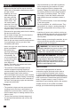
MAINTENANCE Adjusting the Mower Deck Leveling deck Adjust the deck while the mower is on a level surface. Make sure the tires are inflated to the correct pressure. See Technical Data / Transmission. If tires are under or over inflated, the deck cannot be correctly adjusted. Raise the deck to the highest (transport) position. The deck must be adjusted slightly higher in the rear. NOTE: To insure the precision of the leveling procedure, the mower deck drive belt must be installed before leveling the deck. 1.
MAINTENANCE Blade replacement 1. Remove blade bolt by turning counter clockwise. 2. Install new or resharpened blade with stamped GRASS SIDE facing towards ground/grass (down) or THIS SIDE UP facing deck and cutter housing. 3. Seat the blade's opening firmly onto the cutter housing. Restart the mower and engage the blades to use the spinning action to wash away debris. Make sure the hose is away from the mower blades. Do not rinse hot surfaces with cold water. Let unit cool before washing.
MAINTENANCE 12/12 Each year Lubricate with grease gun 1/52 Each Week Filter change 1/365 Each day Oil change Level check General Remove the ignition key to prevent accidental movements during lubrication. When lubricating with an oil can, it must be filled with engine oil. When lubricating with grease, unless otherwise stated, use a high grade molybdenum disulphide grease. For daily use, the machine must be lubricated twice weekly. Clean away unwanted grease after lubrication.
LUBRICATION Engine Oil NOTE: Change the engine oil when the engine is warm. Refer to the engine owner’s manual for the correct replacement oil and filter change recommendations. Wheel and Deck Zerks Use only good quality bearing grease. Grease from well-known brand names (petrochemical companies, etc.) usually maintains a good quality. WARNING! The engine drain plug is located near to the muffler.
TROUBLESHOOTING Problem / Cause Engine will not start Engine overheats Blade switch is engaged Clogged air intake or cooling fins Steering controls are not locked in the outer position Engine overloaded Dead battery Contamination in the carburettor or fuel line Fuel supply shutoff valve is closed or in the incorrect position Clogged fuel filter or fuel line Ignition system faulty Starter does not turn the engine over Dead battery Battery terminal cable contacts are defective Blown fuse Fault in the st
STORAGE Winter Storage The machine should be readied for storage at the end of the mowing season or if it will not be in use for more than 30 days. Fuel allowed to stand for long periods (30 days or more) can leave sticky residues that can clog the carburettor and disrupt engine function. Fuel stabilizers are an acceptable option to prevent the sticky residues that can occur during storage. Add stabilizer to the fuel in the tank or in the storage container.
SCHEMATIC 31
TECHNICAL DATA ENGINE Manufacturer Kawasaki Type FR691V Power 17,2 kW @ 3600 RPM 1) Spark Plug NGK BPR4ES Gap: .030" (0,76 mm) Lubrication Pressure with oil filter Fuel Min 87 octane unleaded (Max ethanol 10%, Max MTBE 15%) Fuel tank capacity 3-1/2 gallons Cooling Air cooled Air filter Standard Alternator 12v 15 amp @ 3600 rpm Starter Electric 13.25 litres TRANSMISSION Transmission Hydrostatic transaxles Steering control Dual levers, foam gripped Speed forward 0-6.
TECHNICAL DATA Torque Specifications Engine crankshaft bolt Deck pulley bolts Lug nuts Spark Plug Torque Blade bolt 50 ft/lb 150 ft/lb 75 ft/lb 16 ft-lb (22 Nm) 90 ft/lb Standard 1/4" fasteners Standard 5/16" fasteners Standard 3/8" fasteners Standard 7/16" fasteners Standard 1/2" fasteners 9 ft/lb 18 ft/lb 33 ft/lb 52 ft/lb 80 ft/lb HEX HEAD CAP SCREWS The torque values shown should be used as a general guideline when specific torque values are not given. U.S.
SERVICE JOURNAL DELIVERY SERVICE Action Date, mtr reading, stamp, sign r r r r r r r Charge and connect the battery Adjust the tire pressure of all wheels to 103 kPa (1 bar) Connect the contact box to the cable for the seat’s safety switch Check that the right quantity of oil is in the engine Adjust the position of the steering controls Fill with fuel and open the fuel shut off valve Start the engine Check: r r r r r r r r r r r r Drive to the two wheels Mower deck pitch and adjustment Safety switch fo
SERVICE JOURNAL AFTER 10 HOURS Action Change the engine oil Date, mtr reading, stamp, sign r DAILY SERVICE Action Clean debris from mower Check engine oil level Check the tire pressures Check underside of deck Check safety system Check fuel system for leaks Inspect safety guards and shields Check brake adjustment Date, mtr reading, stamp, sign r r r r r r r r 25-HOUR SERVICE Action Check the fuel pump’s air filter Sharpen/Replace mower blades if required Check the tire pressures Check battery cables L
SERVICE JOURNAL 100-HOUR SERVICE Action Do the 25-hour service Do the 50-hour service Change the engine oil filter Clean/replace the spark plugs Replace the fuel filter Check V-belts Check / tighten caster wheel axle bolts (at 200 hour intervals) Change the air filter’s paper cartridge Date, mtr reading, stamp, sign r r r r r r r r 300-HOUR SERVICE Action Do the 25-hour service Do the 50-hour service Do the 100-hour service Check / adjust the mower deck Clean the combustion chamber and grind the valve se
2020.05.